
Analog and Digital Electronics 5th Module
Sequential Logic
Flip flops:
A flip flop is an electronic circuit with two stable states that can be used to store binary data. The stored data can be changed by applying varying inputs.
RS flip flop
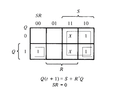
This simple flip-flop circuit has a set input (S) and a reset input (R). In this system, when you Set “S” as active the output “Q” would be high and “Q‘” will be low. Once the outputs are established, the wiring of the circuit is maintained until “S” or “R” go high, or power is turned off. As shown above, it is the simplest and easiest to understand. The two outputs, as shown above, are the inverse of each other. The truth table of SR Flip-Flop is highlighted below.
|
S |
R |
Q |
Q’ |
|
0 |
0 |
0 |
1 |
|
0 |
1 |
0 |
1 |
|
1 |
0 |
1 |
0 |
|
1 |
1 |
∞ |
∞ |
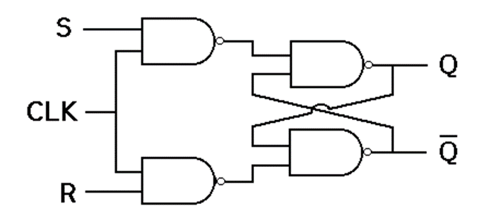
In this circuit diagram, the output is changed (i.e. the stored data is changed) only when you give an active clock signal. Otherwise, even if the S or R is active the data will not change.
D-flip-flop
D flip-flop is a better alternative that is very popular with digital electronics. They are commonly used for counters and shift-registers and input synchronization.

In this, the output can be only changed at the clock edge, and if the input changes at other times, the output will be unaffected.
|
Clock |
D |
Q |
Q’ |
|
↓ » 0 |
0 |
0 |
1 |
|
↑ » 1 |
0 |
0 |
1 |
|
↓ » 0 |
1 |
0 |
1 |
|
↑ » 1 |
1 |
1 |
0 |
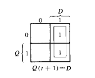
The change of state of the output is dependent on the rising edge of the clock. The output (Q) is same as the input and can only change at the rising edge of the clock.
JK flip flop
Due to the undefined state in the SR flip-flop, another flip-flop is required in electronics. The JK flip-flop is an improvement on the SR flip-flop where S=R=1 is not a problem.

The input condition of J=K=1, gives an output inverting the output state. However, the outputs are the same when one tests the circuit practically.
In simple words, If J and K data input are different (i.e. high and low) then the output Q takes the value of J at the next clock edge. If J and K are both low then no change occurs. If J and K are both high at the clock edge then the output will toggle from one state to the other. JK Flip-Flops can function as Set or Reset Flip-flops
|
J |
K |
Q |
Q’ |
|
0 |
0 |
0 |
0 |
|
0 |
1 |
0 |
0 |
|
1 |
0 |
0 |
1 |
|
1 |
1 |
0 |
1 |
|
0 |
0 |
1 |
1 |
|
0 |
1 |
1 |
0 |
|
1 |
0 |
1 |
1 |
|
1 |
1 |
1 |
0 |

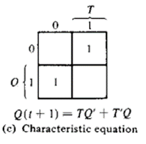
T-flip-flop
A T flip-flop is like a JK flip-flop. These are basically a single input version of JK flip-flops. This modified form of JK flip-flop is obtained by connecting both inputs J and K together. It has only one input along with the clock input.

These flip-flops are called T flip-flops because of their ability to complement its state (i.e.) Toggle, hence the name Toggle flip-flop.
|
T |
Q |
Q (t+1) |
|
0 |
0 |
0 |
|
1 |
0 |
1 |
|
0 |
1 |
1 |
|
1 |
1 |
0 |
Counters:
A Counter is a device which stores (and sometimes displays) the number of times a particular event or process has occurred, often in relationship to a clock signal. Counters are used in digital electronics for counting purpose, they can count specific event happening in the circuit.
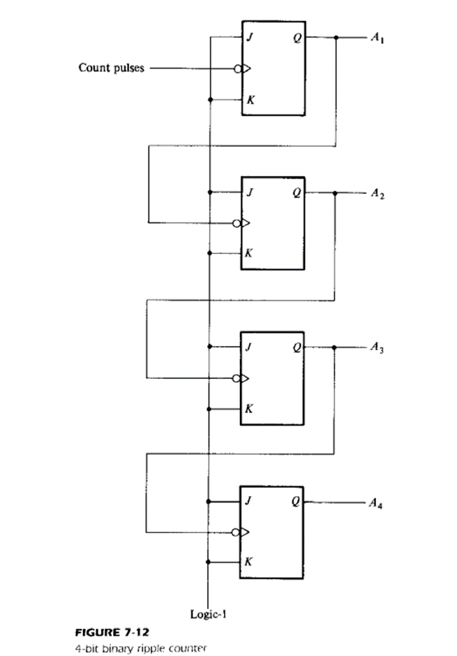
Binary Ripple counter
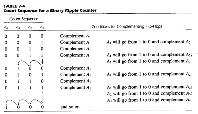
A binary ripple counter consists of a series connection of complementing flip-flops (T or JK Type) with the output of each flip-flop connected to the CP input of the next higher order flip-flop. The flip-flop holding the least significant bit receives the incoming count pulse
Fig shows 4 bit binary ripple counter
BCD ripple counter

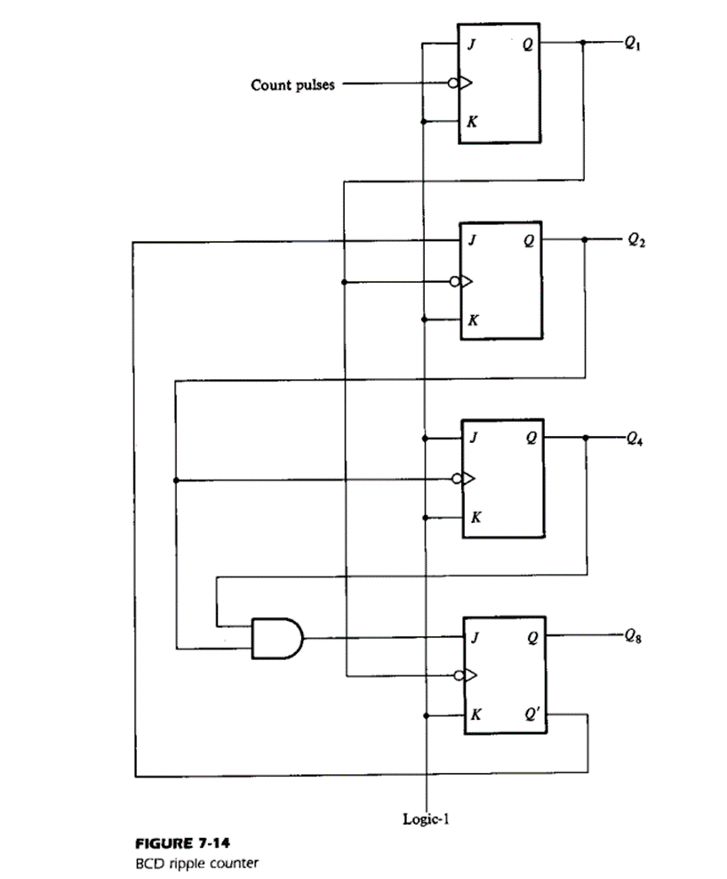
A BCD counter is one of the 4-bit binary counters, which counts from 0 to a pre-determined count with an applied clock signal. When the count reaches the predetermined count value, it resets all the flip-flops and starts to count again from 0. This type of counter is designed by using 4 JK flip flops and counts from 0 to 9, and the result is represented in digital form. After reaching the count of 9 (1001), it resets and starts again.
Synchronous counter:
Synchronous counter are distinguished from ripple counters in that clock pulses are applied to the CP inputs of all flip-flops.
Binary up-down counter
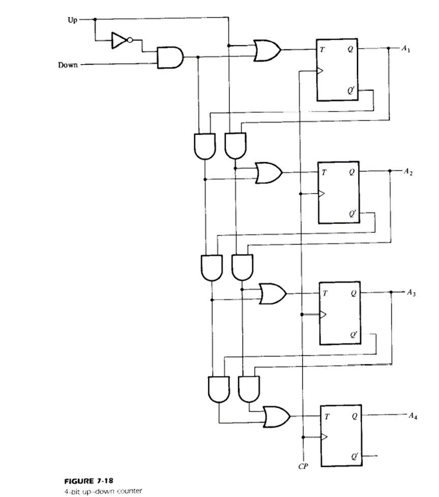
A binary counter capable of counting either up or down is shown in fig. The T flip-flops employed in the circuit may be considered as JK flip flops with the J and K terminals tied together. When the up input control is 1, the circuit counts up since T inputs receive their signals from the values of the previous normal outputs of the flip-flops.
When the down input control is 1 and the up input is 0, the circuit counts down, since the complemented outputs of the previous flip-flops are applied to the T inputs. When the up and down inputs are both 0, the circuit does not change state but remains in the same count. When the up and down inputs are both 1, the circuit counts up.
Binary counter

In a synchronous binary counter, the flip flop in the lowest order position is complemented with every pulse. This means that its J and K inputs must be maintained at logic 1. A flip-flop in any other position is complemented with a pulse provided all the bits in the lower order positions are equal to 1, because the lower order bits (when all 1’s) will change to 0’s on the next count pulse.
Synchronous binary counters have a regular pattern and can easily be constructed with complementing flip flops and gates. The regular pattern can be clearly seen from 4 bit counter in fig

