
Computer Organization 1st Module
Module 1: BASIC STRUCTURE OF COMPUTERS
A computer is a digital electronic machine that can be programmed to carry out sequences of arithmetic or logical operations (computation) automatically. Modern computers can perform generic sets of operations known as programs. These programs enable computers to perform a wide range of tasks.
1.1TYPES OF COMPUTERS
1.1.1 Desktop Computers
• These are most commonly used computers in home, schools and offices.
• This has
→ Processing- & storage-units
→ Video & audio output-units
→ Keyboard & mouse input-units.
1.1.2 Notebook Computers (Laptops)
• This is a compact version of a personal-computer (PC) made as a portable-unit.
1.1.3 Workstations
• These have more computational-power than PC.
1.1.4 Enterprise Systems (Mainframes)
• These are used for business data-processing.
• These have large computational-power and larger storage-capacity than workstations.
• These are referred to as
→ Server at low-end and
→ Super-computers at high end.
1.1.5 Servers
• These have large database storage-units and can also execute requests from other computers.
• These are used in banks & educational institutions.
1.1.6 Super Computers
• These are used for very complex numerical-calculations.
• These are used in weather forecasting, aircraft design and military applications.
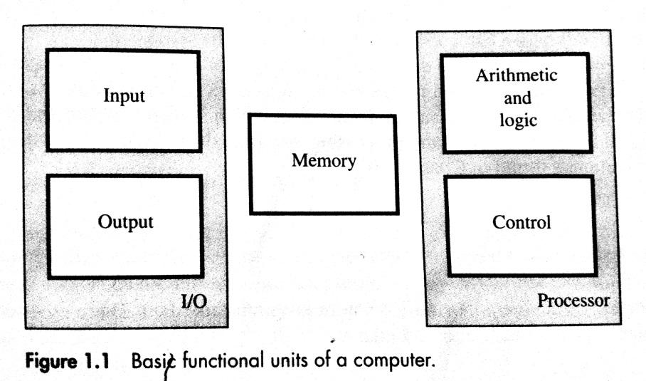
1.2. FUNCTIONAL UNITS
• A computer consists of 5 functionally independent main parts:
1) Input
2) Memory
3) Arithmetic & logic
4) Output
5) Control units.
1.2.1 Input Unit
• The computer accepts the information in the form of program & data through an input-device.
Eg: keyboard
• Whenever a key is pressed, the corresponding letter/digit is automatically translated into its corresponding binary-code and transmitted over a cable to either the memory or the processor.
1.2.2 Memory Unit
• This unit is used to store programs & data.
• There are 2 classes of storage:
1) Primary-storage is a fast-memory that operates at electronic-speed. Programs must be stored in the memory while they are being executed.
2) Secondary-storage is used when large amounts of data & many programs have to be stored. Eg: magnetic disks and optical disks (CD-ROMs).
• The memory contains a large number of semiconductor storage cells(i.e. flip-flops), each capable of storing one bit of information.
• The memory is organized so that the contents of one word can be stored or retrieved in one basic operation.
• Memory in which any location can be reached in a short and fixed amount of time after specifying its address is called RAM (Random Access Memory).
1.2.3 ALU (Arithmetic & Logic Unit)
• This unit is used for performing arithmetic & logical operations.
• Any arithmetic operation is initiated by bringing the required operand into the processor (i.e. registers), where the operation is performed by the ALU.
1.2.4 Output Unit
• This unit is used to send processed-results to the outside world.
Eg: printer, graphic displays etc.
1.2.5 Control Unit
• This unit is used for controlling the activities of the other units (such as memory, I/O device).
• This unit sends control-signals (read/write) to other units and senses their states.
• Data transfers between processor and memory are also controlled by the control-unit through timing-signals.
• Timing-signals are signals that determine when a given action is to take place.
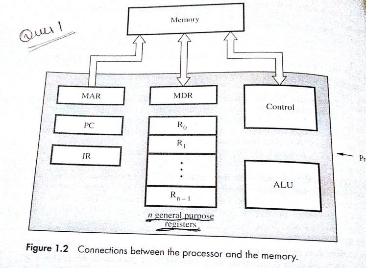
1.3. BASIC OPERATIONAL CONCEPTS
• The processor contains ALU, control-circuitry and many registers.
• The instruction-register (IR) holds the instruction that is currently being executed.
• The instruction is then passed to the control-unit, which generates the timing-signals that determine when a given action is to take place
• The PC (Program Counter) contains the memory-address of the next-instruction to be fetched & executed.
• During the execution of an instruction, the contents of PC are updated to point to next instruction.
• The processor also contains „n‟ general-purpose registers R0 through Rn-1.
• The MAR (Memory Address Register) holds the address of the memory-location to be accessed.
• The MDR (Memory Data Register) contains the data to be written into or read out of the addressed location.
1.3.1 Following are the steps that take place to execute an instruction
• The address of first instruction (to be executed) gets loaded into PC.
• The contents of PC (i.e. address) are transferred to the MAR & control-unit issues Read signal to memory.
• After certain amount of elapsed time, the first instruction is read out of memory and placed into MDR.
• Next, the contents of MDR are transferred to IR. At this point, the instruction can be decoded & executed.
• To fetch an operand, its address is placed into MAR & control-unit issues Read signal. As a result, the operand is transferred from memory into MDR, and then it is transferred from MDR to ALU.
• Likewise required number of operands is fetched into processor.
• Finally, ALU performs the desired operation.
• If the result of this operation is to be stored in the memory, then the result is sent to the MDR.
• The address of the location where the result is to be stored is sent to the MAR and a Write cycle is initiated.
• At some point during execution, contents of PC are incremented to point to next instruction in the program.
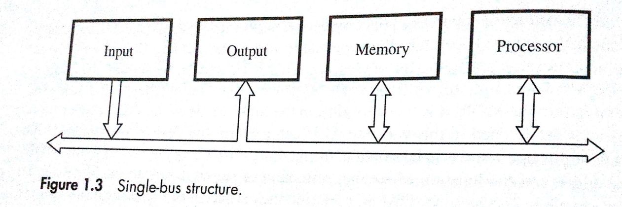
1.4 BUS STRUCTURE
• A bus is a group of lines that serves as a connecting path for several devices.
• Bus must have lines for data transfer, address & control purposes.
• Because the bus can be used for only one transfer at a time, only 2 units can actively use the bus at any given time.
• Bus control lines are used to arbitrate multiple requests for use of the bus.
• Main advantage of single bus: Low cost and flexibility for attaching peripheral devices.
• Systems that contain multiple buses achieve more concurrency in operations by allowing 2 or more transfers to be carried out at the same time. Advantage: better performance. Disadvantage: increased cost.
• The devices connected to a bus vary widely in their speed of operation. To synchronize their operational speed, the approach is to include buffer registers with the devices to hold the information during transfers.
Buffer registers prevent a high-speed processor from being locked to a slow I/O device during a sequence of data transfers.
1.5 PROCESSOR CLOCK
• Processor circuits are controlled by a timing signal called a clock.
• The clock defines regular time intervals called clock cycles.
• To execute a machine instruction, the processor divides the action to be performed into a sequence of basic steps such that each step can be completed in one clock cycle.
• Let P=length of one clock cycle R=clock rate. Relation between P and R is given by
R=1/P
Which is measured in cycles per second.
• Cycles per second is also called hertz(Hz)
1.6 BASIC PERFORMANCE EQUATION
• Let T=processor time required to execute a program
N=actual number of instruction executions
S=average number of basic steps needed to execute one machine instruction R=clock rate in cycles per second
• The program execution time is given by:
T= (N*S)/R -----(1)
• Equation 1 is referred to as the basic performance equation.
• To achieve high performance, the computer designer must reduce the value of T, which means reducing N and S, and increasing R.
→ The value of N is reduced if source program is compiled into fewer machine instructions.
→ The value of S is reduced if instructions have a smaller number of basic steps to perform.
→ The value of R can be increased by using a higher frequency clock.
• Care has to be taken while modifying the values since changes in one parameter may affect the other.
1.7 PERFORMANCE MEASUREMENT
• SPEC(System Performance Evaluation Corporation) selects & publishes the standard programs along with their test results for different application domains
The SPEC rating is computed as follows
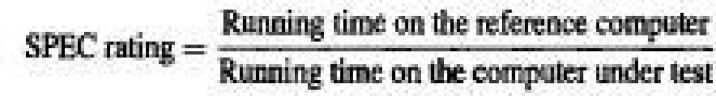
• If SPEC rating=50 means that the computer under test is 50times as fast as reference computer.
• The test is repeated for all the programs in the SPEC suite, and the geometric mean of the results is computed.
Let SPECi be the rating for program i in the suite. The overall SPEC rating for the computer is given by
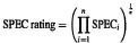
where n=number of programs in the suite
MACHINE INSTRUCTIONS & PROGRAMS
1.8 MEMORY LOCATIONS & ADDRESSES
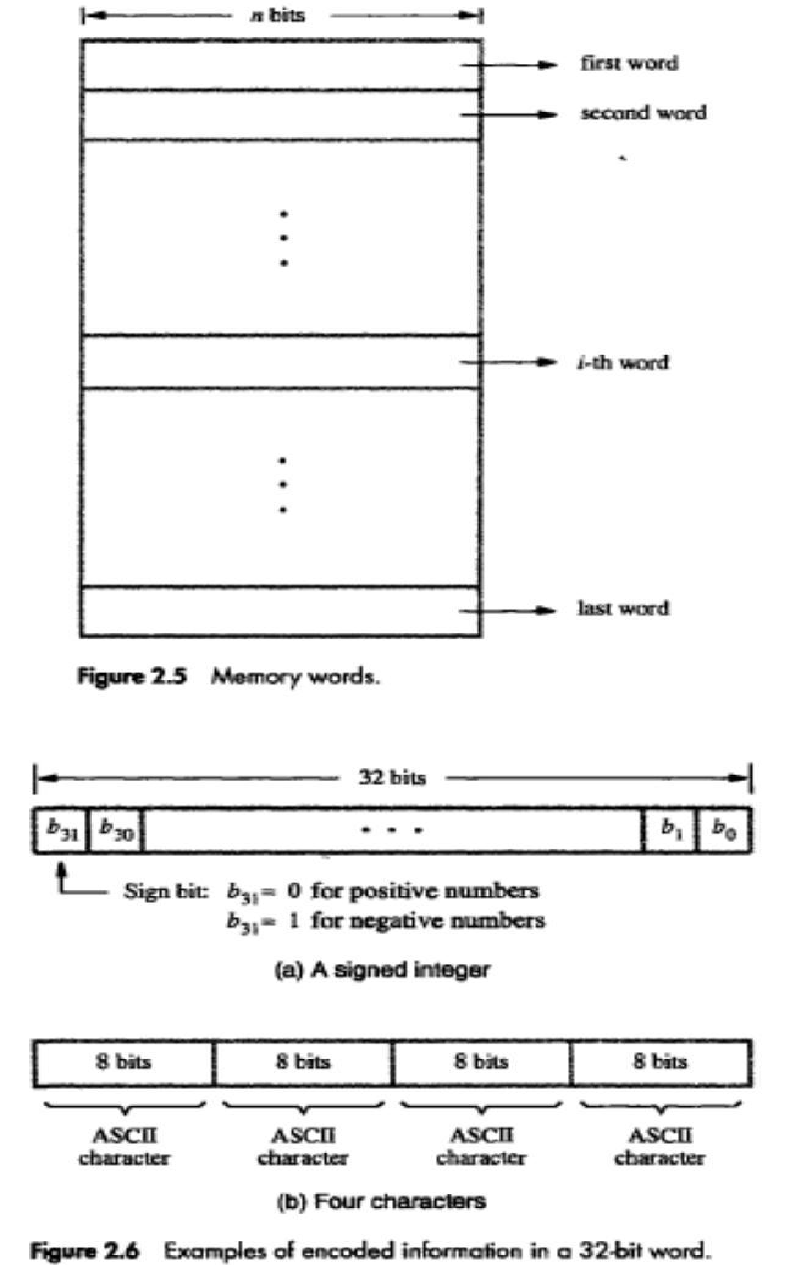
• The memory consists of many millions of storage cells (flip-flops), each of which can store a bit of information having the value 0 or 1 (Figure 2.5).
• Each group of n bits is referred to as a word of information, and n is called the word length.
• The word length can vary from 8 to 64bits.
• A unit of 8 bits is called a byte.
• Accessing the memory to store or retrieve a single item of information (either a word or a byte) requires distinct addresses for each item location. (It is customary to use numbers from 0 through 2k-1 as the addresses of successive locations in the memory).
• If 2k=number of addressable locations, then 2k addresses constitute the address space of the computer. For example, a 24-bit address generates an address space of 224 locations (16MB).
• Characters can be letters of the alphabet, decimal digits, punctuation marks and so on.
• Characters are represented by codes that are usually 8 bits long. E.g. ASCII code
• The three basic information quantities are: bit, byte and word.
• A byte is always 8 bits, but the word length typically ranges from 1 to 64 bits.
• It is impractical to assign distinct addresses to individual bit locations in the memory.
1.8.1 BYTE ADDRESSABILITY
• In byte addressable memory, successive addresses refer to successive byte locations in the memory.
• Byte locations have addresses 0, 1, 2. . . . .
• If the word length is 32 bits, successive words are located at addresses 0, 4, 8. .with each word having 4 bytes.
1.8.2 BIG-ENDIAN AND LITTLE-ENDIAN ASSIGNMENTS
• There are two ways in which byte addresses are arranged.
1) Big-endian assignment: lower byte addresses are used for the more significant bytes of the word
2) Little-endian: lower byte addresses are used for the less significant bytes of the word
• In both cases, byte addresses 0, 4, 8. . . . . are taken as the addresses of successive words in the memory.
1.8.3 WORD ALIGNMENT
• Words are said to be aligned in memory if they begin at a byte address that is a multiple of the number of bytes in a word.
• For example, if the word length is 16(2 bytes), aligned words begin at byte addresses 0, 2, 4 . . . . . And for a word length of 64, aligned words begin at byte addresses 0, 8, 16. . . . . . .
• Words are said to have unaligned addresses, if they begin at an arbitrary byte address.
1.8.4 ACCESSING NUMBERS, CHARACTERS & CHARACTERS STRINGS
• A number usually occupies one word. It can be accessed in the memory by specifying its word address. Similarly, individual characters can be accessed by their byte address.
• There are two ways to indicate the length of the string
→ a special control character with the meaning "end of string" can be used as the last character in the string, or
→ a separate memory word location or processor register can contain a number indicating the length of the string in bytes.
1.9 MEMORY OPERATIONS
• Two basic operations involving the memory are: Load(Read/Fetch) and Store(Write).
• The Load operation transfers a copy of the contents of a specific memory location to the processor. The memory contents remain unchanged.
• The steps for Load operation:
1) Processor sends the address of the desired location to the memory
2) Processor issues „read‟ signal to memory to fetch the data
3) Memory reads the data stored at that address
4) Memory sends the read data to the processor
• The Store operation transfers the information from the processor register to the specified memory location. This will destroy the original contents of that memory location.
• The steps for Store operation are:
1) Processor sends the address of the memory location where it wants to store data
2) Processor issues „write‟ signal to memory to store the data
3) Content of register(MDR) is written into the specified memory location.
1.10 INSTRUCTIONS & INSTRUCTION SEQUENCING
• A computer must have instructions capable of performing 4 types of operations:
1) Data transfers between the memory and the processor registers.
2) Arithmetic and logic operations on data.
3) Program sequencing and control.
4) I/0 transfers.
1.10.1 REGISTER TRANSFER NOTATION (RTN)
• We identify a memory location by a symbolic name (in uppercase alphabets).
For example, LOC, PLACE, NUM etc indicate memory locations.R0, R5 etc indicate processor register. DATAIN, OUTSTATUS etc indicate I/O registers.
• For example,
R<-[LOC] means that the contents of memory location LOC are transferred into processor register R1 (The contents of a location are denoted by placing square brackets around the name of the location). R3<-[R1] + [R2] indicates the operation that adds the contents of registers R1 and R2 ,and then places their sum into register R3.
• This type of notation is known as RTN (Register Transfer Notation).
1.10.2 ASSEMBLY LANGUAGE NOTATION
• To represent machine instructions and programs, assembly language format can be used.
• For example,
Move LOC, R1; This instruction transfers data from memory-location LOC to processor-register R1. The contents of LOC are unchanged by the execution of this instruction, but the old contents of register R1 are overwritten.
Add R1, R2, R3; This instruction adds 2 numbers contained in processor-registers R1 and R2, and places their sum in R3.
• A computer performs its task according to the program stored in memory. A program is a collection of instructions which tell the processor to perform a basic operation like addition, reading from keyboard etc.
• Possible locations that may be involved in data transfers are memory locations, processor registers or registers in the I/O subsystem.
1.10.3 BASIC INSTRUCTION TYPES
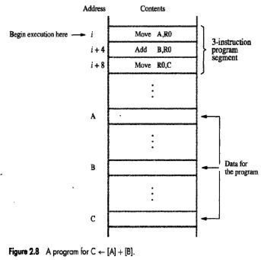
• C=A+B; This statement is a command to the computer to add the current values of the two variables A and B, and to assign the sum to a third variable C.
• When the program is compiled, each variable is assigned a distinct address in memory.
• The contents of these locations represent the values of the three variables
• The statement C<-[A]+[B] indicates that the contents of memory locations A and B are fetched from memory, transferred to the processor, sum is computed and then result is stored in memory location C.
❖ Three-Address Instruction
• The instruction has general format
Operation Source1, Source2, Destination
• For example, Add A, B, C; operands A and B are called the source operands, C is called the destination operand, and Add is the operation to be performed.
❖ Two-Address Instruction
• The instruction has general format
Operation Source, Destination
• For example, Add A, B; performs the operation B<-[A]+[B].
• When the sum is calculated, the result is sent to the memory and stored in location B, replacing the original contents of this location. This means that operand B is both a source and a destination.
• The operation C<-[A]+[B] can be performed by the two-instruction sequence
Move B, C
Add A, C
❖ One-Address Instruction
• The instruction has general format
Operation Source/Destination
• For example, Add A ; Add the contents of memory location A to the contents of the accumulator register and place the sum back into the accumulator.
• Load A; This instruction copies the contents of memory location A into the accumulator and
Store A; This instruction copies the contents of the accumulator into memory location A.
The operation C<-[A]+[B] can be performed by executing the sequence of instructions
Load A
Add B
Store C
• The operand may be a source or a destination depending on the instruction. In the Load instruction, address A specifies the source operand, and the destination location, the accumulator, is implied. On the other hand, C denotes the destination location in the Store instruction, whereas the source, the accumulator, is implied.
❖ Zero-Address Instruction
• The locations of all operands are defined implicitly. The operands are stored in a structure called pushdown stack. In this case, the instructions are called zero-address instructions.
1.10.4 INSTRUCTION EXECUTION & STRAIGHT LINE SEQUENCING
• The program is executed as follows:
1) Initially, the address of the first instruction is loaded into PC (Program counter is a register which holds the address of the next instruction to be executed)
2)Then, the processor control circuits use the information in the PC to fetch and execute instructions, one at a time, in the order of increasing addresses. This is called straight-line sequencing (Figure 2.8)
3) During the execution of each instruction, the PC is incremented by 4 to point to the next instruction.
4) Executing given instruction is a two-phase procedure.
i) In fetch phase, the instruction is fetched from the memory location (whose address is in the PC) and placed in the IR of the processor
ii) In execute phase, the contents of IR is examined to determine which operation is to be performed. The specified operation is then performed by the processor.
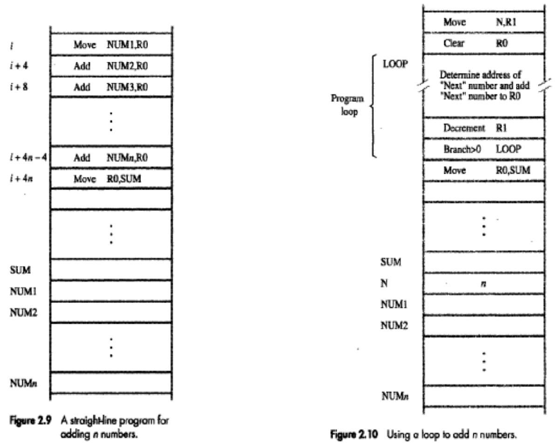
1.10.5 BRANCHING
• Consider the task of adding a list of n numbers (Figure 2.10).
• The loop is a straight line sequence of instructions executed as many times as needed. It starts at location LOOP and ends at the instruction Branch>0.
• During each pass through this loop, the address of the next list entry is determined, and that entry is fetched and added to R0.
• Register R1 is used as a counter to determine the number of times the loop is executed. Hence, the contents of location N are loaded into register R1 at the beginning of the program.
• Within the body of the loop, the instruction Decrement R1 reduces the contents of R1 by 1 each time through the loop.
• Then Branch instruction loads a new value into the program counter. As a result, the processor fetches and executes the instruction at this new address called the branch target.
• A conditional branch instruction causes a branch only if a specified condition is satisfied. If the condition is not satisfied, the PC is incremented in the normal way, and the next instruction in sequential address order is fetched and executed.
1.10.6 CONDITION CODES
• The processor keeps track of information about the results of various operations. This is accomplished by recording the required information in individual bits, called condition code flags.
• These flags are grouped together in a special processor-register called the condition code register (or statue register).
• Four commonly used flags are
→ N (negative) set to 1 if the result is negative, otherwise cleared to 0
→ Z (zero) set to 1 if the result is 0; otherwise, cleared to 0
→ V (overflow) set to 1 if arithmetic overflow occurs; otherwise, cleared to 0
→ C (carry) set to 1 if a carry-out results from the operation; otherwise cleared to 0.

