Computer Organization 3rd Module
ACCESSING I/O DEVICES
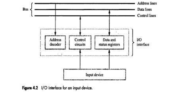
• There are 2 ways to deal with I/O devices (Figure 4.1).
1) Memory mapped I/O
• Memory and I/O devices share a common address-space.
• Any data-transfer instruction (like Move, Load) can be used to exchange information.
• For example, Move DATAIN, R0; this instruction reads data from DATAIN(input-buffer associated with keyboard) & stores them into processor-register R0.
2) In I/O mapped I/O, memory and I/O address-spaces are different.
• Special instructions named IN and OUT are used for data transfer.
• Advantage of separate I/O space: I/O devices deal with fewer address-lines.
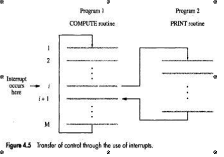
I/O Interface for an Input Device
• Address decoder: decodes address sent on bus, so as to enable input-device (Figure 4.2).
• Data register: holds data being transferred to or from the processor.
• Status register: contains information relevant to operation of I/O device.
• Address decoder, data- and status-registers, and control-circuitry required to coordinate I/O transfers constitute device's interface-circuit.
MECHANISMS USED FOR INTERFACING I/O DEVICES
1) Program Controlled I/O
• Processor repeatedly checks a status-flag to achieve required synchronization between processor& input/output device. (We say that the processor polls the device).
• Main drawback: The processor wastes its time in checking the status of the device before actual data transfer takes place.
2) Interrupt I/O
• Synchronization is achieved by having I/O device send a special signal over bus whenever it is ready for a data transfer operation.
3) Direct Memory Access (DMA)
•This involve sharing the device-interface transfer data directly to or from the memory without continuous involvement by the processor
INTERRUPTS
• I/O device initiates the action insteadof the processor. This is done by sending a special hardwaresignal to the processor called as interrupt (INTR), on the interrupt-request line.
• The processor can be performing its own task without the need to continuously check the I/O device.
• When device gets ready, it will "alert" the processor by sending an interrupt-signal (Figure 4.5).
• The routine executed in response to an interrupt-request is called ISR(Interrupt Service Routine).
• Once the interrupt-request signal comes from the device, the processor has to inform the device that its request has been recognized and will be serviced soon. This is indicated by a special control signal on the bus called interrupt-acknowledge (INTA).
INTERRUPT HARDWARE
• An I/O device requests an interrupt by activating a bus-line called interrupt-request(IR).
• A single IR line can be used to serve „n devices (Figure 4.6).
• All devices are connected to IR line via switches to ground.
• To request an interrupt, a device closes its associated switch. Thus, if all IR signals are inactive(i.e. if all switches are open), the voltage on the IR line will be equal to Vdd.
• When a device requests an interrupt by closing its switch, the voltage on the line drops to 0, causing the INTR received by the processor to go to 1.
• The value of INTR is the logical OR of the requests from individual devices INTR=INTR1+ INTR2+ +INTRn
• A special gate known as open-collector or open-drain are used to drive the INTR line.
• Resistor R is called a pull-up resistor because it pulls the line voltage up to the high-voltage state when the switches are open.
ENABLING & DISABLING INTERRUPTS
• To prevent the system from entering into an infinite-loop because of interrupt, there are 3 possibilities:
1) The first possibility is to have the processor-hardware ignore the interrupt-request line until the execution of the first instruction of the ISR has been completed.
2) The second option is to have the processor automatically disable interrupts before starting the execution of the ISR.
3) In the third option, the processor has a special interrupt-request line for which the interrupt- handling circuit responds only to the leading edge of the signal. Such a line is said to be edge- triggered.
• Sequence of events involved in handling an interrupt-request from a single device is as follows:
1) The device raises an interrupt-request.
2) The program currently being executed is interrupted.
3) All interrupts are disabled (by changing the control bits in the PS).
4) The device is informed that its request has been recognized, and in response, the device deactivates the interrupt-request signal.
5) The action requested by the interrupt is performed by the ISR.
6) Interrupts are enabled again and execution of the interrupted program is resumed.
HANDLING MULTIPLE DEVICES
While handling multiple devices, the issues concerned are:
1. How can processor recognize the device requesting an interrupt?
2. How can processor obtain the starting address of the ISR?
3. How should 2 0r more simultaneous interrupt requests be handled?
Polling
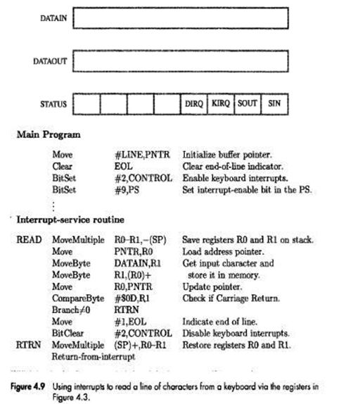
• Information needed to determine whether a device is requesting an interrupt is available in its status-register.
• When a device raises an interrupt-request, it sets IRQ bit to 1 in its status-register (Figure 4.3).
• KIRQ and DIRQ are the interrupt-request bits for keyboard & display.
• Simplest way to identify interrupting device is to have ISR poll all I/O devices connected to bus.
• The first device encountered with its IRQ bit set is the device that should be serviced. After servicing this device, next requests may be serviced.
• Main advantage: Simple & easy to implement.
Main disadvantage: More time spent polling IRQ bits of all devices(that may not be requesting any service).
Vectored Interrupts
• A device requesting an interrupt identifies itself by sending a special-code to processor over bus. (This enables processor to identify individual devices even if they share a single interrupt-request line).
• The code represents starting-address of ISR for that device.
• ISR for a given device must always start at same location.
• The address stored at the location pointed to by interrupting-device is called the interrupt-vector.
• Processor
loads interrupt-vector into PC & executes appropriate ISR
• Interrupting-device must wait to put data on bus only when processor is ready to receive it.
• When processor is ready to receive interrupt-vector code, it activates INTA line.
• I/O device responds by sending its interrupt-vector code & turning off the INTR signal.
CONTROLLING DEVICE REQUESTS
• There are 2 independent mechanisms for controlling interrupt requests.
• At device-end, an interrupt-enable bit in a control register determines whether device is allowed to generate an interrupt request.
• At processor-end, either an interrupt-enable bit in the PS register or a priority structure determines whether a given interrupt-request will be accepted.
INTERRUPT NESTING
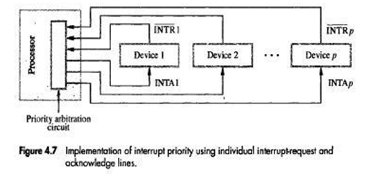
• A multiple-priority scheme is implemented by using separate INTR & INTA lines for each device
• Each of the INTR lines is assigned a different priority-level (Figure 4.7).
• Priority-level of processor is the priority of program that is currently being executed.
• During execution of an ISR, interrupt-requests will be accepted from some devices but not from others depending upon device’s priority.
• Processor accepts interrupts only from devices that have priority higher than its own.
• At the time of execution of an ISR for some device is started, priority of processor is raised to that of the device
• Processor's priority is encoded in a few bits of processor-status (PS) word. This can be changed by program instructions that write into PS. These are called privileged instructions.
• Privileged-instructions can be executed only while processor is running in supervisor-mode.
• Processor is in supervisor-mode only when executing operating-system routines. (An attempt to execute a privileged-instruction while in the user-mode leads to a special type of interrupt called a privileged exception).
SIMULTANEOUS REQUESTS
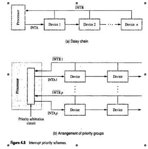
• INTR line is common to all devices (Figure 4.8).
• INTA line is connected in a daisy-chain fashion such that INTA signal propagates serially through devices.
• When several devices raise an interrupt-request and INTR line is activated, processor responds by setting INTA line to 1. This signal is received by device 1.
• Device 1 passes signal on to device 2 only if it does not require any service.
• If device1 has a pending-request for interrupt, it blocks INTA signal and proceeds to put its identifying code on data lines.
• Device that is electrically closest to processor has highest priority.
• Main advantage: This allows the processor to accept interrupt-requests from some devices but not from others depending upon their priorities.
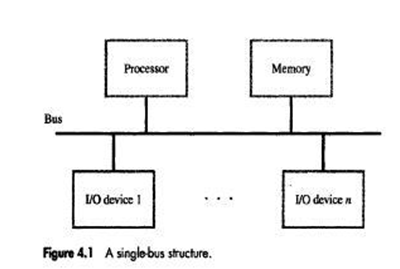
DIRECT MEMORY ACCESS (DMA)
• The transfer of a block of data directly between an external device& main memory without continuous involvement by processor is called as DMA.
• DMA transfers are performed by a control-circuit that is part of I/O device interface. This circuit is called as a DMA controller (Figure 4.19).
• DMA controller performs the functions that would normally be carried out by processor
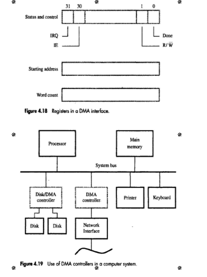
• In controller, 3 registers are accessed by processor to initiate transfer operations (Figure 4.18):
1) Two registers are used for storing starting-address & word-count
2) Third register contains status- & control-flags
• The R/W bit determines direction of transfer.
When R/W=1,controller performs a read operation(i.e. it transfers data from memory to I/O),Otherwise it performs a write operation (i.e. it transfers data from I/O device to memory).
• When done=1, controller
completes transferring a block of data & is ready to receive another command.
• When IE=1, controller raises an interrupt after it has completed transferring a block of data (IE=Interrupt Enable).
• Finally, when IRQ=1, controller requests an interrupt.(Requests by DMA devices for using the bus are always given higher priority than processor requests).
• There are 2 ways in which the DMA operation can be carried out:
1) In one method, processor originates most memory-access cycles. DMA controller is said to "steal" memory cycles from processor. Hence, this technique is usually called cycle stealing.
2) In second method, DMA controller is given exclusive access to main-memory to transfer a block of data without any interruption. This is known as block mode (or burst mode).