Electric Vehicle 2nd Module
Electric vehicles (EVs) use an electric motor for traction, and chemical batteries, fuel cells, ultra capacitors, and/or flywheels for their corresponding energy sources. The electric vehicle has many advantages over the conventional internal combustion engine vehicle (ICEV), such as an absence of emissions, high efficiency, independence from petroleum, and quiet and smooth operation.
Configuration of Electric Vehicles,
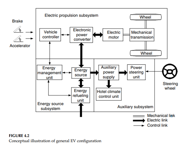
A modern electric drive train is conceptually illustrated in Figure 4.2.1 The drive train consists of three major subsystems: electric motor propulsion, energy source, and auxiliary. The electric propulsion subsystem is comprised of a vehicle controller, power electronic converter, electric motor, mechanical transmission, and driving wheels.
The energy source subsystem involves the energy source, the energy management unit, and the energy refueling unit. The auxiliary subsystem consists of the power steering unit, the hotel climate control unit, and the auxiliary supply unit.
Based on the control inputs from the accelerator and brake pedals, the vehicle controller provides proper control signals to the electronic power converter, which functions to regulate the power flow between the electric motor and energy source.
The backward power flow is due to the regenerative braking of the EV and this regenerated energy can be restored to the energy source, provided the energy source is receptive. Most EV batteries as well as ultra capacitors and flywheels readily possess the ability to accept regenerated energy. The energy management unit cooperates with the vehicle controller to control the regenerative braking and its energy recovery.
It also works with the energy refueling unit to control the refueling unit, and to monitor the usability of the energy source. The auxiliary power supply provides the necessary power at different voltage levels for all the EV auxiliaries, especially the hotel climate control and power steering units.
Different EV Configurations
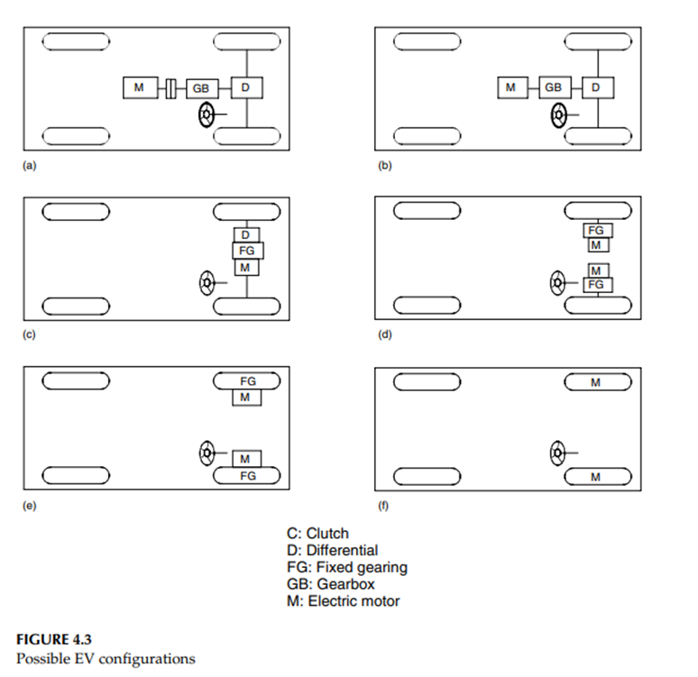
There are a variety of possible EV configurations due to the variations in electric propulsion characteristics and energy sources, as shown in Figure 4.3
(a) Figure 4.3(a) shows the configuration of the first alternative, in which an electric propulsion replaces the IC engine of a conventional vehicle drive train. It consists of an electric motor, a clutch, a gearbox, and a differential. The clutch and gearbox may be replaced by automatic transmission.
The clutch is used to connect or disconnect the power of the electric motor from the driven wheels. The gearbox provides a set of gear ratios to modify the speed-power (torque) profile to match the load requirement.
The differential is a mechanical device (usually a set of planetary gears), which enables the wheels of both sides to be driven at different speeds when the vehicle runs along a curved path.
(b) With an electric motor that has constant power in a long speed range a fixed gearing can replace the multispeed gearbox and reduce the need for a clutch. This configuration not only reduces the size and weight of the mechanical transmission, but also simplifies the drive train control because gear shifting is not needed.
(c) Similar to the drive train in (b), the electric motor, the fixed gearing, and the differential can be further integrated into a single assembly while both axles point at both driving wheels. The whole drive train is further simplified and compacted.
(d) In Figure 4.3(d), the mechanical differential is replaced by using two traction motors. Each of them drives one side wheel and operates at a different speed when the vehicle is running along a curved path.
(e) In order to further simplify the drive train, the traction motor can be placed inside a wheel. This arrangement is the so-called inwheel drive. A thin planetary gear set may be used to reduce the motor speed and enhance the motor torque.
The thin planetary gear set offers the advantage of a high-speed reduction ratio as well as an inline arrangement of the input and output shaft.
(f) By fully abandoning any mechanical gearing between the electric motor and the driving wheel, the out-rotor of a low-speed electric motor in the in-wheel drive can be directly connected to the driving wheel.
The speed control of the electric motor is equivalent to the control of the wheel speed and hence the vehicle speed. However, this arrangement requires the electric motor to have a higher torque to start and accelerate the vehicle.
Performance of Electric Vehicles
A vehicle’s driving performance is usually evaluated by its acceleration time, maximum speed, and gradeability. In EV drive train design, proper motor power rating and transmission parameters are the primary considerations to meet the performance specification. The design of all these parameters depends mostly on the speed–power (torque) characteristics of the traction motor.
· Traction motor characteristics,
Variable-speed electric motor drives usually have the characteristics shown in Figure 4.4. At the low-speed region (less than the base speed as marked in Figure 4.4), the motor has a constant torque. In the high-speed region (higher than the base speed), the motor has a constant power. This characteristic is usually represented by a speed ratio x, defined as the ratio of its maximum speed to its base speed.
In low-speed operations, voltage supply to the motor increases with the increase of the speed through the electronic converter while the flux is kept constant. At the point of base speed, the voltage of the motor reaches the source voltage.
After the base speed, the motor voltage is kept constant and the flux is weakened, dropping hyperbolically with increasing speed. Hence, its torque also drops hyperbolically with increasing speed.
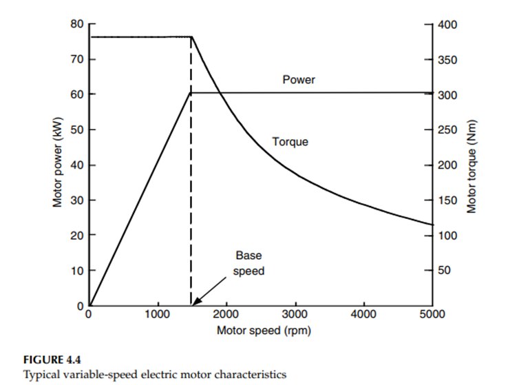
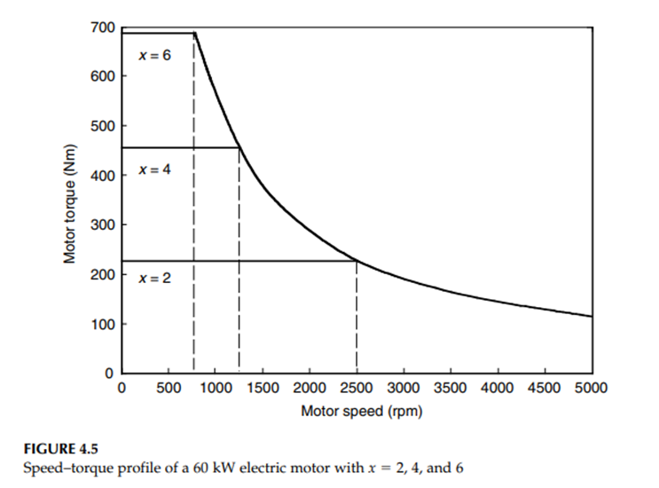
Figure 4.5 shows the torque–speed profiles of a 60 kW motor with different speed ratios x (x=2, 4, and 6). It is clear that with a long constant power region, the maximum torque of the motor can be significantly increased, and hence vehicle acceleration and gradeability performance can be improved and the transmission can be simplified.
· Tractive effort and Transmission requirement,
The tractive effort developed by a traction motor on driven wheels and the vehicle speed are expressed as
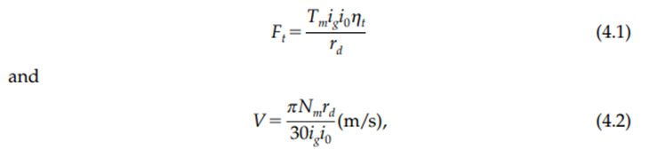
where Tm and Nm are the motor torque output and speed in rpm, respectively, ig is the gear ratio of transmission, i0 is the gear ratio of final drive, ηt is the efficiency of the whole driveline from the motor to the driven wheels, and rdis the radius of the drive wheels.
The use of a multigear or single-gear transmission depends mostly on the motor speed–torque characteristics. That is, at a given rated motor power, if the motor has a long constant power region, a single-gear transmission would be sufficient for a high tractive effort at low speeds. Otherwise, a multigear (more than two gears) transmission has to be used.
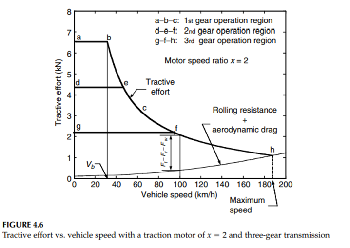
Figure 4.6 shows the tractive effort of an EV, along with the vehicle speed with a traction motor of x=2 and a three-gear transmission. The first gear covers the speed region of a–b–c, the second gear covers d–e–f, and the third gear covers g–f–h.
Figure 4.7 shows the tractive effort with a traction motor of x=6 and a two-gear transmission. The first gear covers the speed region of a–b–c and the second gear d–e–f.
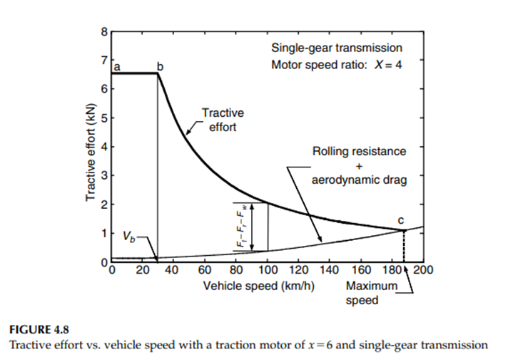
Figure 4.8 shows the tractive effort with a traction motor of x=6 and a single-gear transmission. These three designs have the same tractive effort vs. vehicle speed profiles. Therefore, the vehicles will have the same acceleration and gradeability performance.
· Vehicle performance,
Basic vehicle performance includes maximum cruising speed, gradeability, and acceleration. The maximum speed of a vehicle can be easily found by the intersection point of the tractive effort curve with the resistance curve (rolling resistance plus aerodynamic drag), in the tractive effort vs. vehicle speed diagram shown in Figures 4.6–4.8.
It should be noted that such an intersection point does not exist in some designs, which usually use a larger traction motor or a large gear ratio. In this case, the maximum vehicle speed is determined by the maximum speed of the traction motor as
where Nm max is the allowed maximum rpm of the traction motor and ig min is the minimum gear ratio of the transmission (highest gear). Gradeability is determined by the net tractive effort of the vehicle, Ft-net (F t-net-Ft–Fr-Fw), as shown in Figures 4.6–4.8. At mid- and high speeds, the gradeability is smaller than the gradeability at low speeds
· Tractive effort in normal driving
Actual tractive effort (power) and vehicle speed vary widely with operating conditions, such as acceleration or deceleration, uphill or downhill motion, etc. These variations are associated with the traffic environment as well as the type of vehicles.
City and highway traffic conditions vary greatly, as do the different missions of the vehicles, such as a universal passenger car and vehicles with regular operation routes and schedules. It is difficult to describe the tractive effort and vehicle speed variations in all actual traffic environments accurately and quantitatively.
However, some representative drive cycles (driving schedules) have been developed to emulate typical traffic environments. These drive cycles are represented by the vehicle speeds vs. the operating time while driving on a flat road.
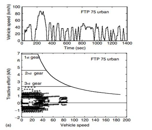
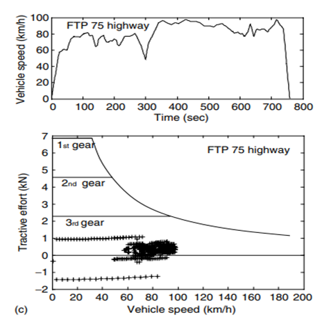
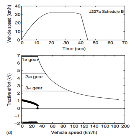
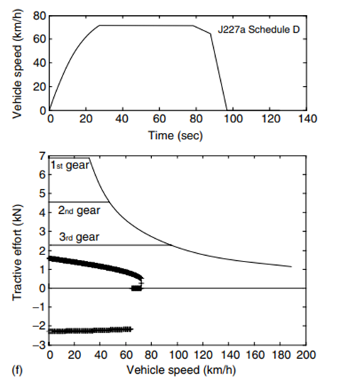
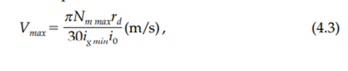
(Speed profile and tractive effort in different representative drive cycles; operating points are marked by ‘+’, (a) FTP 75 urban, (b) FTP 75 highway, (c) US06, (d) J227a schedule B, (e) J227a schedule C, and (f) J227a schedule D)
Some typical drive cycles are illustrated in Figure 4.12, which include (a) FTP75 urban cycle, (b) FTP75 highway cycle, (c) US06 cycle, which is a high-speed and high-acceleration drive cycle, (d) J227a schedule B, (e) J227a schedule C, and (f) J227a schedule D. The J227a series is recommended by the Society of Automotive Engineers in the U.S.A.6 and is applied in the evaluation of EVs and batteries
In a specific drive cycle, the tractive effort of a vehicle can be expressed as
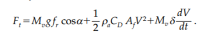
· Energy consumption
In transportation, the unit of energy is usually kilowatt-hour (kWh) rather than joule or kilojoule (J or kJ). The energy consumption per unit distance in kWh/km is generally used to evaluate the vehicle energy consumption. However, for ICE vehicles the commonly used unit is a physical unit of fuel volume per unit distance, such as liters per 100 km (l/100 km). In the U.S., the distance per unit volume of fuel is usually used; this is expressed as miles per gallon (mpg).
On the other hand, for battery-powered EVs, the original energy consumption unit in kWh, measured at the battery terminals, is more suitable. The battery energy capacity is usually measured in kWh and the driving range per battery charge can be easily calculated. Similar to ICE vehicles, l/100 km (for liquid fuels) or kg/100 km (for gas fuels, such as hydrogen) or mpg, or miles per kilogram is a more suitable unit of measurement for vehicles that use gaseous fuels.
Energy consumption is an integration of the power output at the battery terminals. For propelling, the battery power output is equal to resistance power and any power losses in the transmission and the motor drive, including power losses in electronics. The power losses in transmission and motor drive are represented by their efficiencies ηt and ηm, respectively.
Concept of Hybrid Electric Drive Trains,
Basically, any vehicle power train is required to (1) develop sufficient power to meet the demands of vehicle performance, (2) carry sufficient energy onboard to support vehicle driving in the given range, (3) demonstrate high efficiency, and (4) emit few environmental pollutants.
Broadly, a vehicle may have more than one energy source and energy converter (power source), such as a gasoline (or diesel) heat engine system, hydrogen–fuel cell–electric motor system, chemical battery–electric motor system, etc. A vehicle that has two or more energy sources and energy converters is called a hybrid vehicle.
A hybrid vehicle with an electrical power train (energy source energy converters) is called an HEV. A hybrid vehicle drive train usually consists of no more than two power trains. More than two power train configurations will complicate the system.
Figure 5.1 shows the concept of a hybrid drive train and the possible different power flow routes.
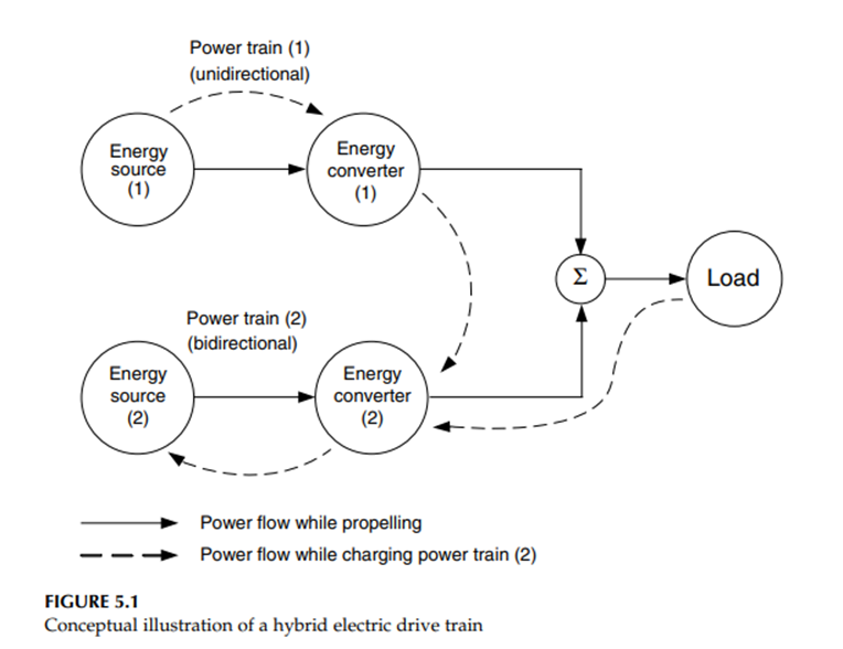
Hybrid drive trains supply the required power by an adapted power train. There are many available patterns of combining the power flows to meet load requirements as described below:
1. Power train 1 alone delivers power to the load
2. Power train 2 alone delivers power to the load
3. Both power train 1 and 2 deliver power to load at the same time
4. Power train 2 obtains power from load (regenerative braking)
5. Power train 2 obtains power from power train 1
6. Power train 2 obtains power from power train 1 and load at the same time
7. Power train 1 delivers power to load and to power train 2 at the same time
8. Power train 1 delivers power to power train 2, and power train 2 delivers power to load
9. Power train 1 delivers power to load, and load delivers power to power train 2
In the case of hybridization with a liquid fuel-IC engine (power train 1) and a battery-electric machine (power train 2), pattern (1) is the engine-alone propelling mode. This may be used when the batteries are almost completely depleted and the engine has no remaining power to charge the batteries, or when the batteries have been fully charged and the engine is able to supply sufficient power to meet the power demands of the vehicle.
Pattern (2) is the pure electric propelling mode, in which the engine is shut off. This pattern may be used in situations where the engine cannot operate effectively, such as very low speed, or in areas where emissions are strictly prohibited.
Pattern (3) is the hybrid traction mode and may be used when a large amount of power is needed, such as during sharp acceleration or steep hill climbing.
Pattern (4) is the regenerative braking mode, by which the kinetic or potential energy of the vehicle is recovered through the electric motor functioning as a generator. The recovered energy is stored in the batteries and reused later on.
Pattern (5) is the mode in which the engine charges the batteries while the vehicle is at a standstill, coasting, or descending a slight grade, in which no power goes into or comes from the load.
Pattern (6) is the mode in which both regenerative braking and the IC engine charge the batteries simultaneously.
Pattern (7) is the mode in which the engine propels the vehicle and charges the batteries simultaneously.
Pattern (8) is the mode in which the engine charges the batteries, and the batteries supply power to the load.
Pattern (9) is the mode in which the power flows into the batteries from the heat engine through the vehicle mass. The typical configuration of this mode is two power trains separately mounted on the front and the rear axle of the vehicle.
The varied operation modes in a hybrid vehicle create more flexibility over a single power train vehicle. With proper configuration and control, applying the specific mode for each special operating condition can optimize overall performance, efficiency, and emissions.
The architecture of Hybrid Electric Drive Trains,
The architecture of a hybrid vehicle is loosely defined as the connection between the components that define the energy flow routes and control ports. Traditionally, HEVs were classified into two basic types: series and parallel.
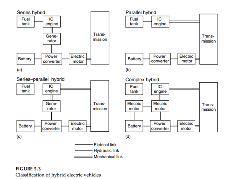
It is interesting to note that, in 2000, some newly introduced HEVs could not be classified into these kinds.5 Therefore, HEVs are now classified into four kinds: series hybrid, parallel hybrid, series–parallel hybrid, and complex hybrid.
In Figure 5.3, a fuel tank-IC engine and a battery-electric motor are taken, respectively, as examples of the primary power source (steady power source) and secondary power source (dynamic power source). Of course, the IC engine can be replaced by other types of power sources, such as fuel cells. Similarly, the batteries can be replaced by ultracapacitors or by flywheels and their combinations.
Series Hybrid Electric Drive Trains
A series hybrid drive train is a drive train where two power sources feed a single powerplant (electric motor) that propels the vehicle. The most commonly found series hybrid drive train is the series hybrid electric drive train shown in Figure 5.4.
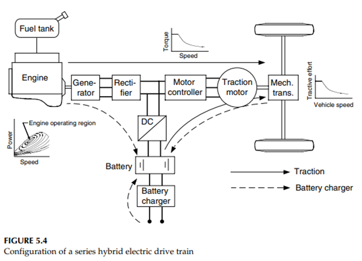
The unidirectional energy source is a fuel tank and the unidirectional energy converter is an engine coupled to an electric generator. The output of the electric generator is connected to an electric power bus through an electronic converter (rectifier). The bidirectional energy source is an electrochemical battery pack, connected to the bus by means of a power electronics converter (DC/DC converter).
The electric power bus is also connected to the controller of the electric traction motor. The traction motor can be controlled either as a motor or a generator, and in forward or reverse motion. This drive train may need a battery charger to charge the batteries by a wall plug-in from the power network.
Series hybrid electric drive trains potentially have the following operation modes:
1. Pure electric mode: The engine is turned off and the vehicle is propelled only by the batteries.
2. Pure engine mode: The vehicle traction power only comes from the engine-generator, while the batteries neither supply nor draw any power from the drive train. The electric machines serve as an electric transmission from the engine to the driven wheels.
3. Hybrid mode: The traction power is drawn from both the engine generator and the batteries.
4. Engine traction and battery charging mode: The engine-generator supplies power to charge the batteries and to propel the vehicle.
5. Regenerative braking mode: The engine-generator is turned off and the traction motor is operated as a generator. The power generated is used to charge the batteries.
6. Battery charging mode: The traction motor receives no power and the engine-generator charges the batteries.
7. Hybrid battery charging mode: Both the engine-generator and the traction motor operate as generators to charge the batteries.
Series hybrid drive trains offer several advantages:
1. The engine is fully mechanical when decoupled from the driven wheels. Therefore, it can be operated at any point on its speed–torque characteristic map, and can potentially be operated solely within its maximum efficiency region as shown in Figure 5.4. The efficiency and emissions of the engine can be further improved by optimal design and control in this narrow region. A narrow region allows greater improvements than an optimization across the entire range. Furthermore, the mechanical decoupling of the engine from the driven wheels allows the use of a high-speed engine. This makes it difficult to power the wheels directly through a mechanical link, such as gas turbines or powerplants, with slow dynamics like the Stirling engine.
2. Because electric motors have near-ideal torque–speed characteristics, they do not need multigear transmissions.Therefore, their construction is greatly simplified and the cost is reduced.
Furthermore, instead of using one motor and a differential gear, two motors may be used, each powering a single wheel. This provides speed decoupling between the two wheels like a differential but also acts as a limited slip differential for traction control purposes.
The ultimate refinement would use four motors, thus making the vehicle an all-wheel-drive without the expense and complexity of differentials and drive shafts running through the frame.
3. Simple control strategies may be used as a result of the mechanical decoupling provided by the electrical transmission.
However, series hybrid electric drive trains have some disadvantages:
1. The energy from the engine is converted twice (mechanical to electrical in the generator and electrical to mechanical in the traction motor). The inefficiencies of the generator and traction motor add up and the losses may be significant.
2. The generator adds additional weight and cost.
3. The traction motor must be sized to meet maximum requirements since it is the only powerplant propelling the vehicle.
Parallel hybrid electric drive trains
(NOTE- If question is asked like explain parallel hybrid train give one example from all three classification)
A parallel hybrid drive train is a drive train in which the engine supplies its power mechanically to the wheels like in a conventional ICE-powered vehicle. It is assisted by an electric motor that is mechanically coupled to the transmission. The powers of the engine and electric motor are coupled together by mechanical coupling, as shown in Figure 5.5.
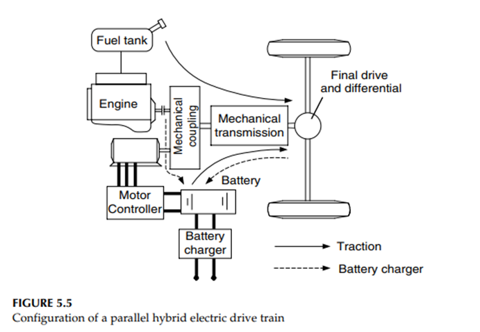
The mechanical combination of the engine and electric motor power leaves room for several different configurations, detailed hereafter
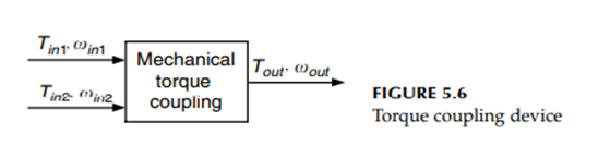
(i) Torque-Coupling Parallel Hybrid Electric Drive Trains The mechanical coupling in Figure 5.5 may be a torque or speed coupling. The torque coupling adds the torques of the engine and the electric motor together or splits the engine torque into two parts: propelling and battery charging. Figure 5.6 conceptually shows a mechanical torque coupling, which has two inputs. One is from the engine and one is from the electric motor. The mechanical torque coupling outputs to the mechanical transmission.
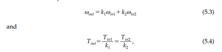
If loss is ignored, the output torque and speed can be described by
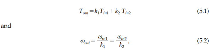
where k1 and k2 are the constants determined by the parameters of torque coupling There are a variety of configurations in torque coupling hybrid drive trains. They are classified into two-shaft and one-shaft designs. In each category, the transmission can be placed in different positions and designed with different gears, resulting in different tractive characteristics. An optimum design will depend mostly on the tractive requirements, engine size and engine characteristics, motor size and motor characteristics, etc.
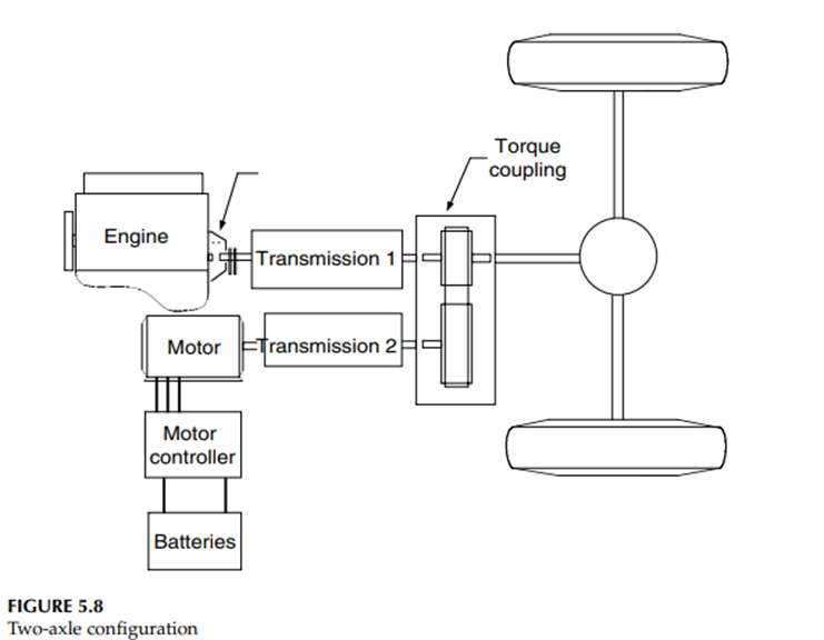
Figure 5.8 shows a two-shaft configuration design, in which two transmissions are used: one is placed between the engine and the torque coupling and other is placed between the motor and torque coupling. Both transmissions may be single or multigear
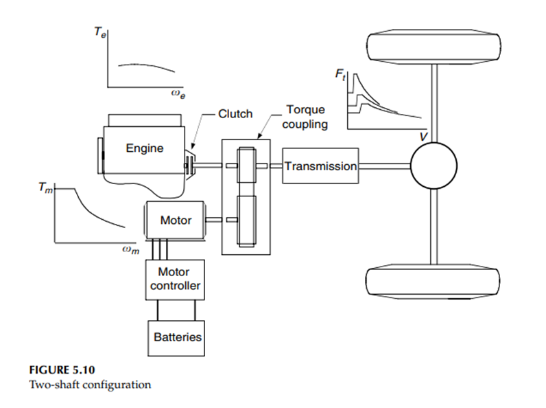
Another configuration of the two-shaft parallel hybrid drive train is shown in Figure 5.10, in which the transmission is located between the torque coupling and drive shaft. This configuration would be suitable in the case when a relatively small engine and electric motor are used, and where a multigear transmission is needed to enhance the tractive effort at low speeds.
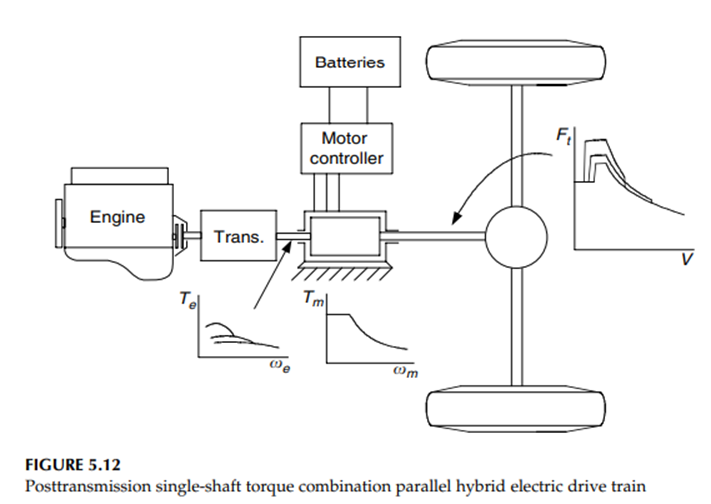
As shown in fig a transmission may be either placed behind an electric motor that is connected to the engine through a clutch or between the engine and the electric motor. The former configuration is referred to as “pretransmission” (the motor is ahead of the transmission, Figure 5.11) and the latter is referred to as “posttransmission” (the motor is behind the transmission, Figure 5.12).
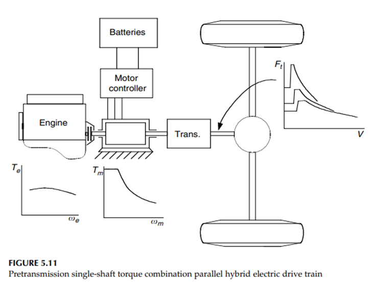
In the pretransmission configuration, both the engine torque and motor torque are modified by the transmission. The engine and motor must have the same speed range. This configuration is usually used in the case of a small motor, referred to as a mild hybrid drive train, in which the electric motor functions as an engine starter, electrical generator, engine power assistant, and regenerative braking.
However, in the posttransmission configuration as shown in Figure 5.12, the transmission can only modify the engine torque while the motor torque is directly delivered to the driven wheels. This configuration may be used in the drive train where a large electric motor with a long constant power
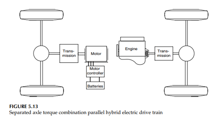
Another torque coupling parallel hybrid drive train is the separated axle architecture, in which one axle is powered by the engine and another is powered by the electric motor (Figure 5.13). The tractive efforts from the two power trains are added through the vehicle chassis and the road. The operating principle is similar to the two-shaft configuration shown in Figure 5.8.
(ii) Speed-Coupling Parallel Hybrid Electric Drive Trains
The powers from two powerplants may be coupled together by coupling their speeds, as shown in Figure 5.14. The characteristics of a speed coupling can be described by
where k1 and k2 are constants associated with the actual design
Figure 5.15 shows two typical speed-coupling devices: one is a planetary gear unit and the other is an electric motor with a floating stator, called a transmotor in this book. A planetary gear unit is a three-port unit consisting of the sun gear, the ring gear, and the yoke labeled 1, 2, and 3, respectively.
The speed and torque relationship between the three ports indicates that the unit is a speed-coupling device, in which the speed, the sun gear, and the ring gear are added together and output through the yoke. The constants k1 and k2 depend only on the radius of each gear or the number of teeth of each gear.
Another interesting device used in speed coupling is an electric motor (called a transmotor), in which the stator, generally fixed to a stationary frame, is released as a power-input port. The other two ports are the rotor and the airgap through which electric energy is converted into mechanical energy

Just like the torque-coupling device, the speed-coupling units can be used to constitute various hybrid drive trains. Figure 5.16 and Figure 5.17 show two examples of hybrid drive trains with speed coupling of the planetary gear unit and an electric transmotor. In Figure 5.16, the engine supplies its power to the sun gear through a clutch and transmission.
The transmission is used to modify the speed–torque characteristics of the engine so as to match the traction requirements. The electric motor supplies its power to the ring gear through a pair of gears. Locks 1 and 2 are used to lock the sun gear and ring gear to the standstill frame of the vehicle in order to satisfy the different operation mode requirements.
The following operation modes can be satisfied:
1. Hybrid traction: When locks 1 and 2 are released the sun gear and ring gear can rotate and both the engine and electric machine supply positive speed and torque (positive power) to the driven wheels.
2. Engine-alone traction: When lock 2 locks the ring gear to the vehicle frame and lock 1 is released only the engine supplies power to the driven wheels.
3. Motor-alone traction: When lock 1 locks the sun gear to the vehicle frame (engine is shut off or clutch is disengaged) and lock 2 is released only the electric motor supplies its power to the driven wheels.
4. Regenerative braking: Lock 1 is set in locking state, the engine is shut off or clutch is disengaged, and the electric machine is controlled in regenerating operation (negative torque). The kinetic or potential energy of the vehicle can be absorbed by the electric system.
5. Battery charging from the engine: When the controller sets a negative speed for the electric machine, the electric machine absorbs energy from the engine.
The drive train, consisting of the transmotor as shown in Figure 5.17, has a structure similar to that in Figure 5.16. Locks 1 and 2 are used to lock the stator to the vehicle frame and the stator to the rotor, respectively. This drive train can fulfill all the operation modes mentioned above.
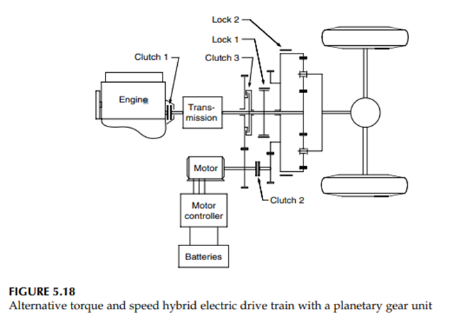
(iii) Torque-Coupling and Speed-Coupling Parallel Hybrid Electric Drive Trains
By combining torque and speed coupling together, one may constitute a hybrid drive train in which torque and speed coupling states can be alternatively chosen.
Figure 5.18 shows such an example. When the torque coupling operation mode is chosen as the current mode, lock 2 locks the ring gear of the planetary unit to the vehicle frame, while clutches 1 and 3 are engaged and clutch 2 is disengaged. The powers of the engine and the electric motor are added together by adding their torques together (refer to equation [5.1]), and then delivered to the driven wheels. In this case, the engine torque and the electric motor are decoupled, but their speeds have a fixed relationship
When the speed-coupling mode is chosen as the current operating mode, clutch 1 is engaged, whereas clutches 2 and 3 are disengaged, and locks 1 and 2 release the sun gear and the ring gear. The speed of the yoke, connected to the drive wheels, is the combination of engine speed and motor speed. But the engine torque, the electric motor torque, and the torque on the driven wheels are kept in a fixed relationship.
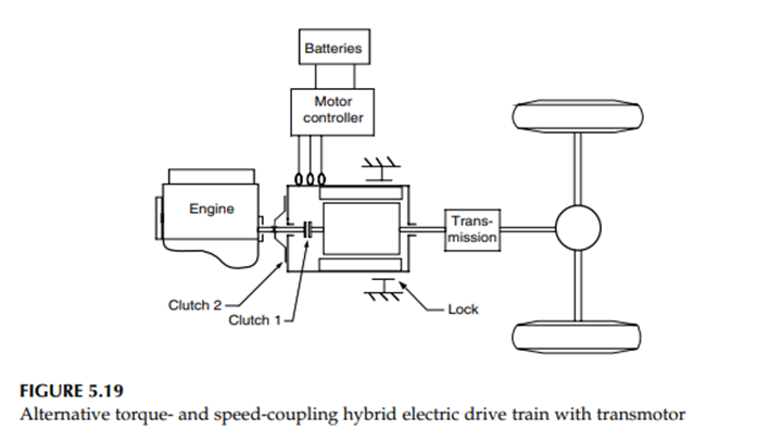
The planetary gear unit traction motor in Figure 5.18 can be replaced by a transmotor to constitute a similar drive train as shown in Figure 5.19.12 When clutch 1 is engaged to couple the engine shaft to the rotor shaft of the transmotor, clutch 2 is disengaged to release the engine shaft from the rotor of the transmotor and the lock is activated to set the stator of the transmotor to the vehicle frame. The drive train then works in the torque-coupling mode. On the other hand, when clutch 1 is disengaged and clutch 2 is engaged and the lock is released, the drive train works in the speed-coupling mode