
Electric Vehicle 3rd Module
Energy storage requirements,
There are a number of requirements for energy storage applied in an automotive application, such as
Specific energy - which Is the energy per unit mass of the energy source. The specific energies are shown without taking containment into consideration. The specific energy of hydrogen and natural gas would be significantly lower than that of gasoline when containment is considered.
Specific power- Similar to specific energy, specific power is the power available per unit mass from the source
Operating life- The operating life of a battery is the number of deep discharge cycles obtainable in its lifetime or the number of service years expected in a certain application.
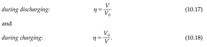
Energy Efficiency - The energy or power losses during battery discharging and charging appear in the form of voltage loss. Thus, the efficiency of the battery during discharging and charging can be defined at any operating point as the ratio of the cell operating voltage to the thermodynamic voltage, that is:
Cost - . And above all, the cost of batteries must be reasonable for EVs and HEVs to be commercially viable.
It also includes Maintenance requirement, management, environmental adaptation and friendliness, and safety. For allocation on an EV, specific energy is the first consideration since it limits the vehicle range.
On the other hand, for HEV applications, specific energy becomes less important and specific power is the first consideration, because all the energy is from the energy source (engine or fuel cell) and sufficient power is needed to ensure vehicle performance, particularly during acceleration, hill climbing, and regenerative braking. Of course, other requirements should be fully considered in vehicle drive train development
Additional technical issues include methods and designs to balance the battery segments or packs electrically and thermally, accurate techniques to determine a battery’s state of charge, and recycling facilities of battery component
Battery BASICS (Components of battery cell)
The energy stored in a battery is the difference in free energy between chemical components in the charged and discharged states. This available chemical energy in a cell is converted into electrical energy only on demand, using the basic components of a unit cell, which are the positive and negative electrodes, the separators, and the electrolytes. The electrochemically active ingredient of the positive or negative electrode is called the active material. Chemical oxidation and reduction processes take place at the two electrodes, thereby bonding and releasing electrons, respectively. The electrodes must be electronically conducting and are located at different sites, separated by a separator, as shown in Figure 3.1.
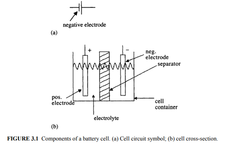
The components of the battery cell are described as follows:
1. Positive electrode: The positive electrode is an oxide or sulfide or some other compound that is capable of being reduced during cell discharge. This electrode consumes electrons from the external circuit during cell discharge. Examples of positive electrodes are lead oxide (PbO2) and nickel oxyhydroxide (NiOOH). The electrode materials are in the solid state.
2. Negative electrode: The negative electrode is a metal or an alloy that is capable of being oxidized during cell discharge. This electrode generates electrons in the external circuit during cell discharge. Examples of negative electodes are lead (Pb) and cadmium (Cd). Negative electrode materials are also in the solid state within the battery cell.
3. Electrolyte: The electrolyte is the medium that permits ionic conduction between positive and negative electrodes of a cell. The electrolyte must have high and selective conductivity for the ions that take part in electrode reactions, but it must be a nonconductor for electrons in order to avoid self-discharge of batteries.
The electrolyte may be liquid, gel, or solid material. Also, the electrolyte can be acidic or alkaline, depending on the type of battery. Traditional batteries such as lead-acid and nickel-cadmium use liquid electrolytes. In lead-acid batteries, the electrolyte is the aqueous solution of sulfuric acid [H2SO4(aq)]. Advanced batteries currently under development for EVs, such as sealed lead-acid, nickelmetal-hydride (NiMH), and lithium-ion batteries use an electrolyte that is gel, paste, or resin. Lithium-polymer batteries use a solid electrolyte.
4. Separator: The separator is the electrically insulating layer of material that physically separates electrodes of opposite polarity. Separators must be permeable to the ions of the electrolyte and may also have the function of storing or immobilizing the electrolyte. Present day separators are made from synthetic polymers
There are two basic types of batteries: primary batteries and secondary batteries. Batteries that cannot be recharged and are designed for a single discharge are known as primary batteries. Examples of these are the lithium batteries used in watches, calculators, cameras, etc., and the manganese dioxide batteries used to power toys, radios, torches, etc.
Batteries that can be recharged by flowing current in the direction opposite to that during discharge are known as secondary batteries. The chemical reaction process during cell charge operation when electrical energy is converted into chemical energy is the reverse of that during discharge. The batteries needed and used for EVs and HEVs are all secondary batteries, because they are recharged during regeneration cycles of vehicle operation or during the battery recharging cycle in the stopped condition using a charger.
Battery Pack
The batteries are made of unit cells containing the chemical energy that is convertible to electrical energy. One or more of these electrolytic cells are connected in series to form one battery. The grouped cells are enclosed in a casing to form a battery module. A battery pack is a collection of these individual battery modules connected in a series and parallel combination to deliver the desired voltage and energy to the power electronic drive system
Types of Batteries
The major types of rechargeable batteries considered for EV and HEV applications are:
• Lead-acid (Pb-acid)
• Nickel-cadmium (NiCd)
• Nickel-metal-hydride (NiMH)
• Lithium-ion (Li-ion)
• Lithium-polymer (Li-poly)
• Sodium-sulfur (NaS)
• Zinc-air (Zn-Air)
LEAD-ACID BATTERY
Lead-acid batteries have been the most popular choice of batteries for EVs. Leadacid batteries can be designed to be high powered and are inexpensive, safe, and reliable. A recycling infrastructure is in place for them. However, low specific energy, poor cold temperature performance, and short calendar and cycle life are among the obstacles to their use in EVs and HEVs.
The lead-acid battery has a history that dates to the middle of the 19th century, and it is currently a mature technology. The first lead-acid battery was produced as early as in 1859. In the early 1980s, over 100,000,000 lead-acid batteries were produced per year. The long existence of the lead-acid battery is due to the following
•Relatively low cost
• Easy availability of raw materials (lead, sulfur)
• Ease of manufacture
• Favorable electromechanical characteristics
The battery cell operation consists of a cell discharge operation, when the energy is supplied from the battery to the electric motor to develop propulsion power, and a cell charge operation, when energy is supplied from an external source to store energy in the battery.
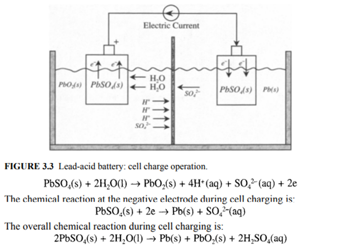
CELL CHARGE OPERATION
The cell charge operation (Figure 3.3) is the reverse of the cell discharge operation. During cell charging, lead sulfate is converted back to the reactant states of lead and lead oxide. The electrons are consumed from the external source at the negative electrode, while the positive electrode releases the electrons. The current flows into the positive electrode from the external source, thereby delivering electrical energy into the cell, where it gets converted into chemical energy. The chemical reaction at the positive electrode during cell charging is:
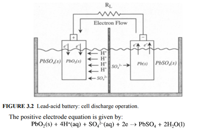
CELL DISCHARGE OPERATION
In the cell discharge operation (Figure 3.2), electrons are consumed at the positive electrode, the supply of which comes from the negative electrode. The current flow is, therefore, out of the positive electrode into the motor-load, with the battery acting as the source.
A highly porous structure is used for the positive electrode to increase the PbO2 (s)/electrolyte contact area, which is about 50 to 150 m2 per Ah of battery capacity. This results in higher current densities, as PbO2 is converted to PbSO4 (s). As discharge proceeds, the internal resistance of the cell rises due to PbSO4formation and decreases the electrolyte conductivity as H2SO4 is consumed. PbSO4(s) deposited on either electrode in a dense, fine-grain form can lead to sulfatation. The discharge reaction is largely inhibited by the buildup of PbSO4, which reduces cell capacity significantly from the theoretical capacity.

The electrons are released at the negative electrode during discharge operation. The production of PbSO4(s) can degrade battery performance by making the negative electrode more passive.

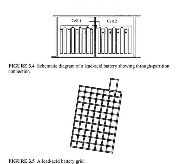
Construction
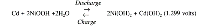
Construction of a typical battery consists of positive and negative electrode groups (elements) interleaved to form a cell. The through partition connection in the battery is illustrated in Figure 3.4. The positive plate is made of stiff paste of the active material on a lattice-type grid, which is shown in Figure 3.5.
The grid, made of a suitably selected lead alloy, is the framework of a portable battery to hold the active material. The positive plates can be configured in flat pasted or tubular fashion. The negative plates are always manufactured as pasted types
NICKEL-CADMIUM BATTERY
Nickel-cadmium (NiCd) and nickel-metal-hydride (NiMH) batteries are examples of alkaline batteries with which electrical energy is derived from the chemical reaction of a metal with oxygen in an alkaline electrolyte medium. The specific energy of alkaline batteries is lowered due to the addition of weight of the carrier metal. The NiCd battery employs a nickel oxide positive electrode and a metallic cadmium negative electrode. The net reaction occurring in the potassium hydroxide (KOH) electrolyte is:
The practical cell voltage is 1.2 to 1.3 V, and the atomic mass of cadmium is 112. The specific energy of NiCd batteries is 30 to 50 Wh/kg, which is similar to that of lead-acid batteries.
The advantages of NiCd batteries are superior low-temperature performance compared to lead-acid batteries, flat discharge voltage, long life, and excellent reliability. The maintenance requirements of the batteries are also low.
The biggest drawbacks of NiCd batteries are the high cost and the toxicity contained in cadmium. Environmental concerns may be overcome in the long run through efficient recycling, but the insufficient power delivered by the NiCd batteries is another important reason for not considering these batteries for EV and HEV applications. The drawbacks of the NiCd batteries led to the rapid development of NiMH batteries, which are deemed more suitable for EV and HEV applications
NICKEL-METAL-HYDRIDE (NiMH) BATTERY
The nickel-metal-hydride battery is a successor to the nickel-hydrogen battery and is already in use in production HEVs. In NiMH batteries, the positive electrode is a nickel oxide similar to that used in a NiCd battery, while the negative electrode is a metal hydride where hydrogen is stored.
The concept of NiMH batteries is based on the fact that fine particles of certain metallic alloys, when exposed to hydrogen at certain pressures and temperatures, absorb large quantities of the gas to form the metal-hydride compounds.
Furthermore, the metal hydrides are able to absorb and release hydrogen many times without deterioration. The two electrode chemical reactions in a NiMH battery are:
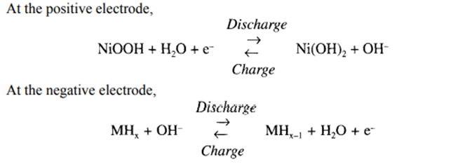
M stands for metallic alloy, which takes up hydrogen at ambient temperature to form the metal hydride MHX. The negative electrode consists of a compressed mass of fine metal particles. The proprietary alloy formulations used in NiMH are known as AB5 and AB2 alloys. In the AB5 alloy, A is the mixture of rare earth elements, and B is partially substituted nickel.
In the AB2 alloy, A is titanium or zirconium, and B is again partially substituted nickel. The AB2 alloy has a higher capacity for hydrogen storage and is less costly. The operating voltage of NiMH is almost the same as that of NiCd, with flat discharge characteristics.
The capacity of the NiMH is significantly higher than that of NiCd, with specific energy ranging from 60 to 80 Wh/kg. The specific power of NiMH batteries can be as high as 250 W/kg
LI-ION BATTERY
Lithium metal has high electrochemical reduction potential (3.045 V) and the lowest atomic mass (6.94), which shows promise for a battery of 3 V cell potential when combined with a suitable positive electrode. The interest in secondary lithium cells soared soon after the advent of lithium primary cells in the 1970s, but the major difficulty was the highly reactive nature of the lithium metal with moisture, restricting the use of liquid electrolytes
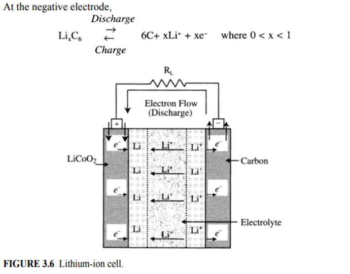
Discovery in the late 1970s by researchers at Oxford University that lithium can be intercalated (absorbed) into the crystal lattice of cobalt or nickel to form LiCoO2 or LiNiO2 paved the way toward the development of Li-ion batteries. The use of metallic-lithium is bypassed in Li-ion batteries by using lithium intercalated (absorbed) carbons (LixC) in the form of graphite or coke as the negative electrode, along with the lithium metallic oxides as the positive electrode.The graphite is capable of hosting lithium up to a composition of LiC6.
The cell discharge operation in a lithium ion cell using LiCoO2 is illustrated in Figure 3.6. During cell discharge, lithium ions (Li+) are released from the negative electrode that travels through an organic electrolyte toward the positive electrode.
In the positive electrode, the lithium ions are quickly incorporated into the lithium compound material. The process is completely reversible. The chemical reactions at the electrodes are as follows:

During cell charge operation, lithium ions move in the opposite direction from the positive electrode to the negative electrode. The nominal cell voltage for a Li-ion battery is 3.6 V, which is equivalent to three NiMH or NiCd battery cells.
Lithium-ion batteries have high specific energy, high specific power, high energy efficiency, good high-temperature performance, and low self-discharge. The components of Li-ion batteries are also recyclable. These characteristics make Li-ion batteries highly suitable for EV and HEV and other applications of rechargeable batteries.
LI-POLYMER BATTERY
Lithium-polymer evolved out of the development of solid state electrolytes, i.e., solids capable of conducting ions but that are electron insulators. The solid state electrolytes resulted from research in the 1970s on ionic conduction in polymers.
These batteries are considered solid state batteries, because their electrolytes are solids. The most common polymer electrolyte is polyethylene oxide compounded with an appropriate electrolyte salt. The most promising positive electrode material for Li-poly batteries is vanadium oxide V6O13. This oxide interlaces up to eight lithium atoms per oxide molecule with the following positive electrode reaction:

Li-poly batteries have the potential for the highest specific energy and power. The solid polymers, replacing the more flammable liquid electrolytes in other type of batteries, can conduct ions at temperatures above 60°C. The use of solid polymers also has a great safety advantage in case of EV and HEV accidents.
The thin Li-poly cell gives the added advantage of forming a battery of any size or shape to suit the available space within the EV or HEV chassis. The main disadvantage of the Li-poly battery is the need to operate the battery cell in the temperature range of 80 to 120°C.
Li-poly batteries with high specific energy, initially developed for EV applications, also have the potential to provide high specific power for HEV applications. The other key characteristics of the Li-poly are good cycle and calendar life
ZINC-AIR BATTERY
Zinc-air batteries have a gaseous positive electrode of oxygen and a sacrificial negative electrode of metallic zinc. The practical zinc-air battery is only mechanically rechargeable by replacing the discharged product, zinc hydroxide, with fresh zinc electrodes. The discharged electrode and the potassium hydroxide electrolyte are sent to a recycling facility. In a way, the zinc-air battery is analogous to a fuel cell, with the fuel being the zinc metal.
A module of zinc air batteries tested in German Mercedes Benz postal vans had a specific energy of 200 Wh/kg, but only a modest specific power of 100 W/kg at 80% depth-of discharge.
With present-day technology, the range of zinc-air batteries can be between 300 to 600 km between recharges.
These batteries include iron-air and aluminum-air batteries, in which iron and aluminum are, respectively, used as the mechanically recyclable negative electrode. The practical metal-air batteries have two attractive features: the positive electrode can be optimized for discharge characteristics, because the battery is recharged outside of the battery; and the recharging time is rapid, with a suitable infrastructure
SODIUM-SULFUR BATTERY
Sodium, similar to lithium, has a high electrochemical reduction potential (2.71 V) and low atomic mass (23.0), making it an attractive negative electrode element for batteries. Moreover, sodium is abundant in nature and available at a low cost.
Sulfur, which is a possible choice for the positive electrode, is also a readily available and low-cost material. The use of aqueous electrolytes is not possible due to the highly reactive nature of sodium, and because the natures of solid polymers like those used for lithium batteries are not known. The solution of electrolyte came from the discovery of beta-alumina by scientists at Ford Motor Company in 1966.
Beta-alumina is a sodium aluminum oxide with a complex crystal structure. Despite several attractive features of NaS batteries, there are several practical limitations. The cell operating temperature in NaS batteries is around 300°C, which requires adequate insulation as well as a thermal control unit. This requirement forces a certain minimum size of the battery, limiting the development of the battery for only EVs, a market that is not yet established.
Another disadvantage of NaS batteries is the absence of an overcharge mechanism. At the top-of-charge, one or more cells can develop a high resistance, which pulls down the entire voltage of the series-connected battery cells
Practical limitations and manufacturing difficulties of NaS batteries have led to the discontinuation of its development programs, especially when the simpler concept of sodium-metal-chloride batteries was developed
SODIUM-METAL-CHLORIDE BATTERY
The sodium-metal-chloride battery is a derivative of the sodium-sulfur battery with intrinsic provisions of overcharge and overdischarge. The construction is similar to that of the NaS battery, but the positive sulfur electrode is replaced by nickel chloride (NiCl2) or a mixture of nickel chloride and ferrous chloride (FeCl2). The negative electrode and the electrolyte are the same as in a NaS battery. The schematic diagram of a NaNiCl2 cell is shown in Figure 3.7
The basic cell reactions for the nickel chloride and ferrous chloride positive electrodes are as follows:
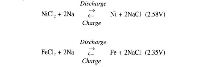
On charging after assembly, the positive electrode compartment is formed of the respective metal, and the negative electrode compartment is formed of sodium. This procedure has two significant advantages: pure sodium is manufactured in situ through diffusion in beta-alumina, and the raw materials for the battery (common salt and metal powder) are inexpensive
Sodium chloride batteries are commonly known as ZEBRA batteries, which originally resulted from a research collaboration between scientists from the United Kingdom and South Africa in the early 1980s. ZEBRA batteries have been shown to be safe under all conditions of use. They have high potential for being used as batteries for EVs and HEVs. There are several test programs utilizing the ZEBRA batteries.
BATTERY PARAMETERS
Storage Capacity:
It determines for number of hours for which the battery can be discharged at a constant current to a defined cutoff voltage. It is represented by the Coulomb SI unit (Amperes per second) but since this unit is usually very small, the Ampere-hour (Ah) unit is used instead (1 Ah represents 3600 C).
The value of this capacity depends on the ambient temperature, the age of the battery, and the discharge rate. The higher the discharge rate, the lower the capacity, although it affects each battery technology differently. Additional to the Ampere-hour unit, the storage capacity can also be defined in Watt-hours (Wh=V x Ah), where 1 Wh represents 3600 J.
Energy Density:
The energy density is the amount of energy that can be stored, per cubic meter of battery volume, expressed in Watt-hour per cubic meter (Wh/m3 ). This is a very important parameter to select a specific battery technology for transportation applications, where space availability is critical.
Specific Power:
This parameter is defined as the power capacity per kilogram of battery, in W/kg . Some battery technologies offer high energy density but low specific power, which means that even though they can store a large amount of energy, they can only supply a small amount of power instantly.
In transportation terms, this would mean that a vehicle could run for a long distance, at low speed. On the contrary, batteries with high specific power usually have low energy density, because high discharge currents usually reduce the available energy rapidly (e.g., high acceleration)
Cell Voltage:
The cell voltage is determined by the equilibrium thermodynamic reactions that take place inside the cell, however, this value is often difficult to measure and therefore, the open circuit voltage (OCV) measured between the anode and cathode terminals is used instead.
For some battery technologies (e.g., lead-acid), the OCV can be used as a basic estimate of the state of charge (SoC). Another measure often used is the closed circuit voltage (CCV), which depends on the load current, state of charge, and cell’s usage history. Finally, battery manufacturers provide the nominal voltage value, from the cell’s characterization and therefore, cannot be experimentally verified
Charge and Discharge Current:
During the discharging process in a battery, electrons flow from the anode to the cathode through the load, to provide with the required current and the circuit is completed in the electrolyte. During the charging process, an external source supplies with the charging current and the oxidation takes place at the positive electrode while the reduction takes place at the negative electrode.
For practical purposes, the term C-rate is used to express the charge or discharge current relative to the rated capacity. For example, a discharge rate of 1 C means that the battery will be fully discharged in 1 h.
State of Charge:
The state of charge (SoC) defines the amount of stored energy relative to the total energy storage capacity of the battery. Depending on the battery technology, different methods are used to estimate this value.
Depth of Discharge:
Often referred to as DoD(in %), this parameter expresses the battery capacity that has been discharged relative to the maximum capacity. Each battery technology supports different maximum recommended levels of DoD to minimize its impact on the overall cycle life.
Cycle Life:
The cycle life determines the number of charge/discharge cycles that the battery can experience before it reaches a predetermined energy capacity or other performance criteria. The current rate at which the battery is charged/discharged as well as environmental conditions (e.g., temperature and humidity) and the DoD can affect this number, since it is originally calculated by the manufacturer based on specific charge and discharge conditions.
Self-discharge:
This parameter defines the reduction in energy capacity of the battery under no-load conditions (e.g., open circuit), as a result of internal short-circuits and chemical reactions.
This parameter can be affected by environmental conditions such as temperature and humidity, as well as the DoD and the battery’s charge/discharge history. Additionally, this parameter is particularly important for long-term shelf storage of batteries.
Round-Trip Efficiency:
Due to internal losses and material degradation, not all the energy supplied to the battery during charging can be recovered during discharge.
The amount of energy that can be taken from the battery during the discharging process over the energy supplied determines the round-trip efficiency. This efficiency is sensitive to the charging and discharging currents. At higher currents, thermal losses increase and therefore the efficiency is reduced
Fuel Cell basic principle and operation
A fuel cell is an electrochemical device that produces electricity by means of a chemical reaction, much like a battery. The major difference between batteries and fuel cells is that the latter can produce electricity as long as fuel is supplied, while batteries produce electricity from stored chemical energy and, hence, require frequent recharging.
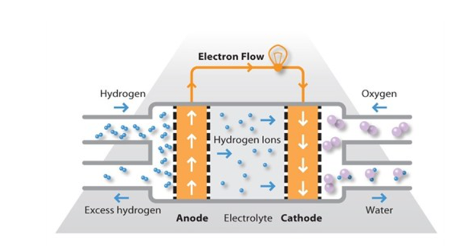
The basic structure of a fuel cell (Figure 4.1) consists of an anode and a cathode, similar to a battery. The fuel supplied to the cell is hydrogen and oxygen. The concept of fuel cell is the opposite of electrolysis of water, where hydrogen and oxygen are combined to form electricity and water. The hydrogen fuel supplied to the fuel cell consists of two hydrogen atoms per molecule chemically bonded together in the form H2.
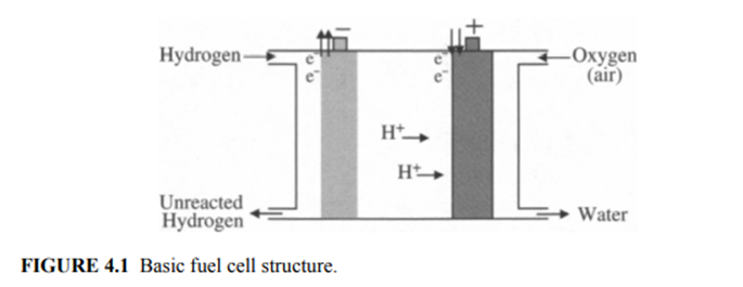
This molecule includes two separate nuclei, each containing one proton, while sharing two electrons. The fuel cell breaks apart these hydrogen molecules to produce electricity. The exact nature of accomplishing the task depends on the fuel cell type, although what remains the same for all fuel cells is that this reaction takes place at the anode.
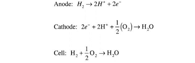
The hydrogen molecule breaks into four parts at the anode due to the chemical reaction, releasing hydrogen ions and electrons. A catalyst speeds the reaction, and an electrolyte allows the two hydrogen ions, which essentially are two single protons, to move to the cathode through the electrolyte placed between the two electrodes.
The flow of electrons from the anode to the cathode through the external circuit is what produces electricity. For the overall cell reaction to complete, oxygen or air must be passed over the cathode. The cathode reaction takes place in two stages. First, the bond between the two oxygen atoms in the molecule breaks and then each ionized oxygen atom grabs two electrons coming from the anode through the external circuit to become negatively charged.
The negatively charged oxygen atoms are balanced by the positively charged hydrogen atoms at the cathode, and the combination produces H2O commonly known as water. The chemical reaction taking place in a fuel cell is as follows:
Types of Fuel Cells
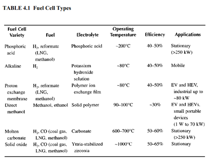
Alkaline fuel cells (AFCs)
Alkaline fuel cells (AFCs) were one of the first fuel cell technologies to be developed and were originally used by NASA in the space programme to produce both electricity and water aboard spacecraft. AFCs continued to be used on NASA space shuttles through the programme, alongside a limited number of commercial applications.
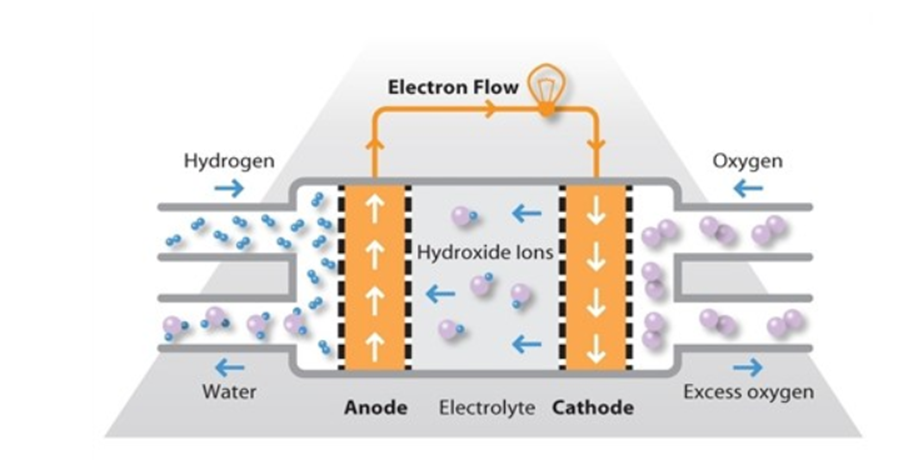
AFCs use an alkaline electrolyte such as potassium hydroxide in water and are generally fuelled with pure hydrogen. The first AFCs operated at between 100 degree Celsius and 250 degree Celsius but typical operating temperatures are now around 70 degree Celsius.
As a result of the low operating temperature, it is not necessary to employ a platinum catalyst in the system and instead, a variety of non-precious metals can be used as catalysts to speed up the reactions occurring at the anode and cathode. Nickel is the most commonly used catalyst in AFC units
PEMFC and its operation,
The proton exchange membrane fuel cell (PEMFC) uses a water based acidic polymer membrane as its electrolyte, with platinum-based electrodes. PEMFC cells operate at relatively low temperatures (below 100 degree Celsius) and can tailor electrical output to meet dynamic power requirements.
Due to the relatively low temperatures and the use of precious metal-based electrodes, these cells must operate on pure hydrogen. PEMFC cells are currently the leading technology for light duty vehicles and materials handling vehicles, and to a less extent for stationary and other applications
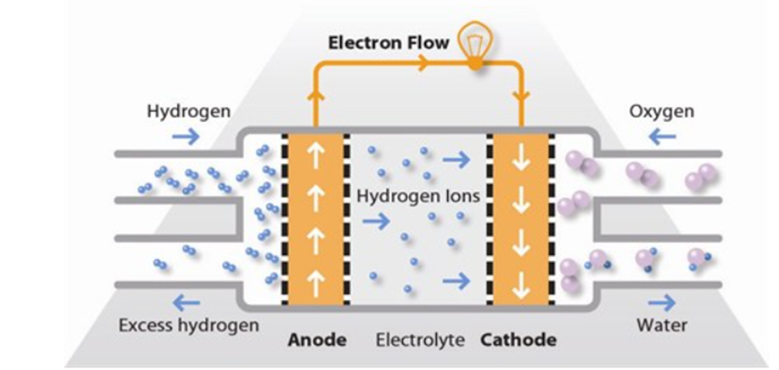
Hydrogen fuel is processed at the anode where electrons are separated from protons on the surface of a platinum based catalyst. The protons pass through the membrane to the cathode side of the cell while the electrons travel in an external circuit, generating the electrical output of the cell.
On the cathode side, another precious metal electrode combines the protons and electrons with oxygen to produce water, which is expelled as the only waste product; oxygen can be provided in a purified form, or extracted at the electrode directly from the air.
A variant of the PEMFC which operates at elevated temperatures is known as the high temperature PEMFC (HT PEMFC), By changing the electrolyte from being water based to a mineral acid based system, HT PEMFCs can operate up to 200 degrees Celsius. This overcomes some of the current limitations with regard to fuel purity with HT PEMFCs able to process reformate containing small quantities of Carbon Monoxide (CO).
The balance of plant can also be simplified through elimination of the humidifier. HT PEMFCs are not superior to low temperature PEMFCs; both technologies find niches where their benefits are preferable.
Direct Methanol Fuel Cell (DMFC)
Direct methanol fuel cell (DMFC) is a relatively recent addition to the suite of fuel cell technologies; it was invented and developed in the 1990s by researchers at several institutions in the united states including NASA and Jet Propulsion Laboratory.
It is similar to the PEM cell in that it uses a polymer membrane as an electrolyte. However, the platinum- ruthenium catalyst on the DMFC anode is able to draw the hydrogen from liquid methanol, eliminating the need for a fuel reformer. Therefore pure methanol can be used as fuel hence the name.
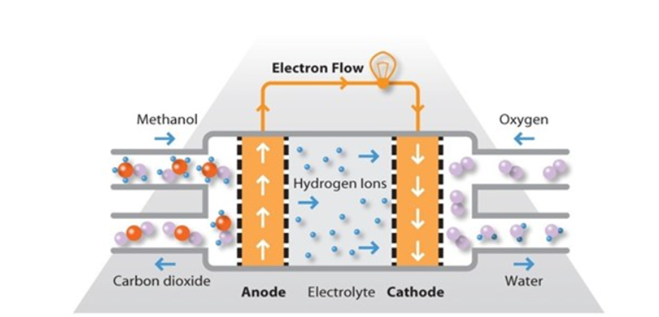
Methanol offers several advantages as a fuel. It is inexpensive but has a relatively high energy density and can be easily transported and stored. It can be supplied to the fuel cell unit from a liquid reservoir which can be topped up, or in catridges which can be quicly changed out when spent
DMFCs operate in temperature range from 60 degree Celsius to 130 degree celsiius and tend to be used in applications with modest power requirements, such as mobile electronic devices or chargers and portable power packs.
One particular application for DMFCs which is seeing commercial traction in various countries is the use of DMFC power units for materials handling vehicles. By switching to fuel cells, the warehouse can refuel their trucks in a manner of minutes, compared to the hours it would take to charge a battery.
The fuel cells also eliminate the need for a battery charging infrastructure within the warehouse thereby making more floor space available for other uses.
Molten Carbonate Fuel Cell (MCFC)
Molten carbonate fuel cells (MCFCs) use a molten carbonate salt suspended in a porous ceramic matrix as the electrolyte. Salts commonly used include lithium carbonate, potassium carbonate and sodium carbonate.
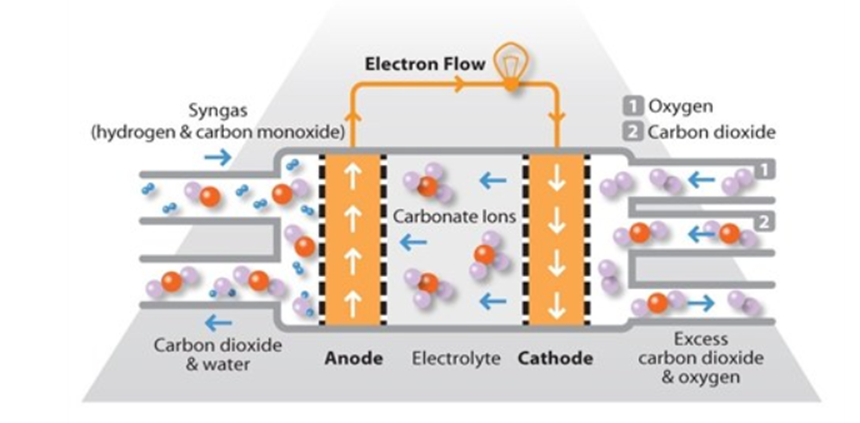
They operate at higher temperature around 650 degree C and there are several advantages associated with thus. Firstly the high operating temperature dramatically improves reaction kinetics and thus it is not necessary to boost these with a noble metal catalyst. The higher temperature also makes the cell less prone to carbon monoxide poisoning than lower temperature systems.
As a result MCFC systems can operate on a variety of different fuels, including coal – derived fuel gas, methane or natural gas, eliminating the need for external reformers.
Disadvantages associated with MCFC units arise from using a liquid electrolyte rather than a solid and the requirement to inject carbon di oxide at the cathode as carbonate ions are consume n reactions occurring at the cathode
MCFCs are used in large stationary power generation. Most fuel cell power plants of megawatt capacity use MCFCs as do large combined heat and power (CHP) and combined cooling and power (CCP) Plants.
These fuel cells can work at upto 60 percent efficiency for fuel to electricity conversion and overall efficiencies can be over 80 percent in CHP or CCP applications where the process heat is also utilised.
Phosphoric Acid Fuel Cell (PAFC)
Phosphoric acid fuel cells (PAFCs) consist of an anode and a cathode made of a finely dispersed platinum catalyst on carbon and a silicon carbide structure that holds the phosphoric acid electrolyte.
They are quiet resistant to poisoning by carbon monoxide but tend to have lower efficiency than other fuel cell types in producing electricity. However these cells operate at moderately high temperatures of around 180 degree Celsius and overall efficiency can be over 80% if this process heat is harnessed for cogeneration.
This type of fuel cell is used in stationary power generators with output in the 100kW to 400kW range to power many commercial premises around the world, and they also find applications in large vehicles such as buses. Most fuel cell units sold before 2001 used PAFC technology
Solid Oxide Fuel Cell
Solid oxide fuel cells work at very high temperatures, the highest of all the fuel cell types at around 800ºC to 1,000°C. They can have efficiencies of over 60% when converting fuel to electricity; if the heat they produced is also harnessed; their overall efficiency in converting fuel to energy can be over 80%.
SOFCs use a solid ceramic electrolyte, such as zirconium oxide stabilized with yttrium oxide, instead of a liquid or membrane. Their high operating temperature means that fuels can be reformed within the fuel cell itself, eliminating the need for external reforming and allowing the units to be used with a variety of hydrocarbon fuels. They are also relatively resistant to small quantities of sulfur in the fuel, compared to other types of fuel cell, and can hence be used with coal gas.
A further advantage of the high operating temperature is that the reaction kinetics are improved, removing the need for a metal catalyst. There are however some disadvantages to the high temperature: these cells take longer to start up and reach operating temperature, they must be constructed of robust, heat-resistant materials, and they must be shielded to prevent heat loss.
There are three different SOFC geometries of SOFC: planar, coplanar and micro-tubular. In the planar design, components are assembled in flat stacks where the air and hydrogen traditionally flow through the unit via channels built into the anode and cathode. In the tubular design, air is supplied to the inside of an extended solid oxide tube (which is sealed at one end) while fuel flows around the outside of the tube. The tube itself forms the cathode and the cell components are constructed in layers around the tube.
SOFCs are used extensively in large and small stationary power generation.
Super-capacitors.
Capacitors are devices that store energy by the separation of equal positive and negative electrostatic charges. The basic structure of a capacitor consists of two conductors, known as plates, separated by a dielectric, which is an insulator. The power densities of conventional capacitors are extremely high (~1012 W/m3), but the energy density is very low (~50 Wh/m3). These conventional capacitors are commonly known as “electrolytic capacitors.”
Supercapacitors and ultracapacitors are derivatives of conventional capacitors, where energy density has been increased at the expense of power density to make the devices function more like a battery.
Power density and energy density of supercapacitors and ultracapacitors are of the order of 106W/m3 and 104 Wh/m3, respectively. Energy density is much lower compared to those of batteries (~5 to 25×104 Wh/m3), but the discharge times are much faster (110 s compared to ~5×10³ s of batteries), and the cycle life is much more (~105 compared to 100 to 1000 of batteries).
Supercapacitors contain an electrolyte that enables the storage of electrostatic charge in the form of ions, in addition to conventional energy storage in electrostatic charges, like in an electrolytic capacitor. The internal functions in a supercapacitor do not involve electrochemical reaction. The electrodes in supercapacitors are made of porous carbon with high internal surface area to help absorb the ions and provide a much higher charge density than is possible in a conventional capacitor. The ions move much more slowly than electrons, enabling a much longer time constant for charging and discharging compared to electrolytic capacitors.
Ultracapacitors are versions of electrolytic capacitors that use electrochemical systems to store energy in a polarized liquid layer at the interface between an ionically conducting electrolyte and an electrically conducting electrode. Energy storage capacity is increased by increasing the surface area of the interface, similar to that in a supercapacitor. Electrochemical (also known as Faradaic) reactions in ultracapacitors are confined to the surface layers and, hence, are fully reversible with a long cycle life

