
Electric Vehicle 4th Module
Electric Propulsion (EV Consideration)
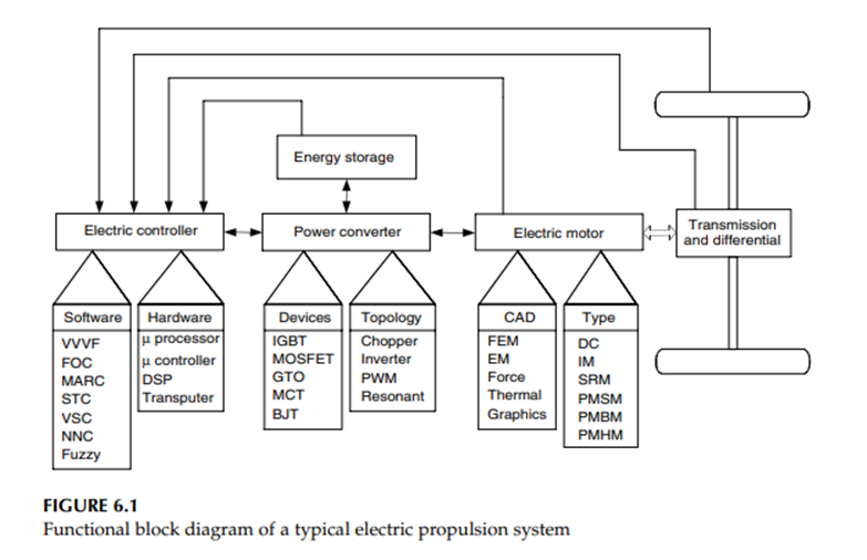
Electric propulsion systems are at the heart of electric vehicles (EVs) and hybrid electric vehicles (HEVs). They consist of electric motors, power converters, and electronic controllers. The electric motor converts the electric energy into mechanical energy to propel the vehicle, or, vice versa, to enable regenerative braking and/or to generate electricity for the purpose of charging the onboard energy storage.
The power converter is used to supply the electric motor with proper voltage and current. The electronic controller commands the power converter by providing control signals to it, and then controls the operation of the electric motor to produce proper torque and speed, according to the command from the drive.
The electronic controller can be further divided into three functional units — sensor, interface circuitry, and processor. The sensor is used to translate measurable quantities such as current, voltage, temperature, speed, torque, and flux into electric signals through the interface circuitry.
These signals are conditioned to the appropriate level before being fed into the processor. The processor output signals are usually amplified via the interface circuitry to drive power semiconductor devices of the power converter. The functional block diagram of an electric propulsion system is illustrated in Figure 6.1.
The choice of electric propulsion systems for EVs and HEVs mainly depends on a number of factors, including driver expectation, vehicle constraints, and energy source. Driver expectation is defined by a driving profile, which includes the acceleration, maximum speed, climbing capability, braking, and range. Vehicle constraints, including volume and weight, depend on vehicle type, vehicle weight, and payload.
The energy source relates to batteries, fuel cells, ultra capacitors, flywheels, and various hybrid sources. Thus, the process of identifying the preferred feature and package options for electric propulsion has to be carried out at the system level. The interaction of subsystems and the likely impacts of system trade-offs must be examined.
Classification of electric motor drives for EV and HEV applications
Differing from the industrial applications of motors, the motors used in EVs and HEVs usually require frequent starts and stops, high rates of acceleration/deceleration, high torque and low-speed hill climbing, low torque and high-speed cruising, and a very wide speed range of operation. The motor drives for EVs and HEVs can be classified into two main groups, namely the commutator motors and commutator less motors as illustrated in Figure 6.2.
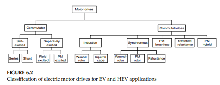
Commutator motors mainly are the traditional DC motors, which include series excited, shunt excited, compound excited, separately excited, and permanent magnet (PM) excited motors. DC motors need commutators and brushes to feed current into the armature, thus making them less reliable and unsuitable for maintenance-free operation and high speed.
In addition, winding excited DC motors have low specific power density. Nevertheless, because of their mature technology and simple control, DC motor drives have been prominent in electric propulsion systems.
Induction motors are widely accepted as a commutator less motor type for EV and HEV propulsion. This is because of their low cost, high reliability, and maintenance-free operation. However, conventional control of induction motors such as variable-voltage variable-frequency (VVVF) cannot provide the desired performance.
However, these EV and HEV motors using FOC still suffer from low efficiency at low light loads and limited constant-power operating range. By replacing the field winding of conventional synchronous motors with PMs, PM synchronous motors can eliminate conventional brushes, slip rings, and field copper losses.
Actually, these PM synchronous motors are also called PM brushless AC motors, or sinusoidal-fed PM brushless motors, because of their sinusoidal AC current and brushless configuration. Since these motors are essentially synchronous motors, they can run from a sinusoidal or pulsed waveform modulation supply (PWM supply) without electronic commutation.
When PMs are mounted on the rotor surface, they behave as nonsalient synchronous motors because the permeability of PMs is similar to that of air. By burying those PMs inside the magnetic circuit of the rotor, the saliency causes an additional reluctance torque, which leads to facilitating a wider speed range at constant power operation.
On the other hand, by abandoning the field winding or PMs while purposely making use of the rotor saliency, synchronous reluctance motors are generated. These motors are generally simple and inexpensive, but with relatively low output power.
By virtually inverting the stator and rotor of PM DC motors (commutator), PM brushless DC motors are generated. It should be noted that the term “DC” may be misleading, since it does not refer to a DC current motor. Actually, these motors are fed by rectangular AC current, and are hence also known as rectangular-fed PM brushless motors. The most obvious advantage of these motors is the removal of brushes.
Recently, sensorless control technologies have been developed in the Power Electronics and Motor Drive Laboratory at Texas A&M University. Switched reluctance (SR) motors have been recognized to have considerable potential for EV and HEV applications.
SR motors have the definite advantages of simple construction, low manufacturing cost, and outstanding torque–speed characteristics for EV and HEV applications. Although they possess simplicity in construction, this does not imply any simplicity of their design and control.
DC motor drives and speed control
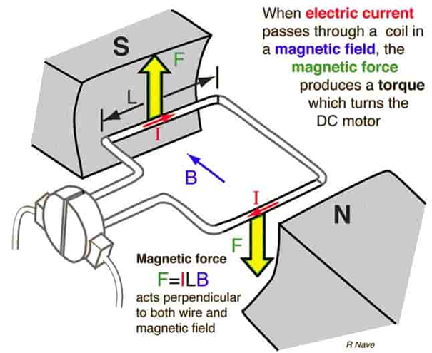
The very basic construction of a DC motor contains a current carrying armature, connected to the supply end through commutator segments and brushes. The armature is placed in between north pole and south pole of a permanent or an electromagnet as shown in the diagram above.
As soon as we supply direct current in the armature, a mechanical force acts on it due to the electromagnetic effect of the magnet on armature conductors. Now to go into the details of the operating principle of DC motor it is important that we have a clear understanding of Fleming’s left-hand ruleto determine the direction of the force acting on the armature conductors of DC motor.
According to Fleming’s left-hand rule when an electric current passes through a coil in a magnetic field, the magnetic force produces a torque that turns the DC motor.
F = BIL Newtons
If a current carrying conductor is placed in a magnetic fieldperpendicularly, then the conductor experiences a force in the direction mutually perpendicular to both the direction of field and the current carrying conductor. Fleming’s Left-Hand Rule can determine the direction of rotation of the motor.
This rule says if we extend the index finger, middle finger and thumb of our left-hand perpendicular to each is such a way that middle finger is in the direction of current in the conductor, and index finger is along the direction of magnetic field, i.e., north to south pole, then thumb indicates the direction of the created mechanical force.
Speed Control of DC Motor Drives:
The Speed Control of DC Motor Drives can be any of the following methods:
- Armature voltage control
- Field flux control
- Armature resistance control
Speed-torque curves of dc motors for these methods of speed control are shown in Figs. 5.16 to 5.18.
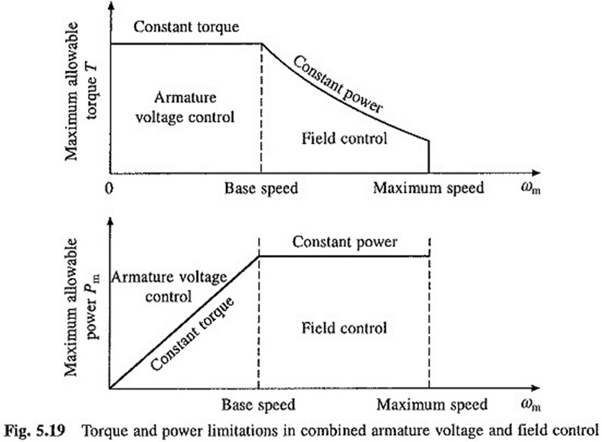
Armature voltage control is preferred because of high efficiency, good transient response and good speed regulation. But it can provide Speed Control of DC Motor Drives only below base (rated) speed because the armature voltage cannot be allowed to exceed rated value. For speed control above base speed, field flux control is employed.
In a normally designed motor, the maximum speed can be allowed up to twice rated speed and in specially designed machines it can be six times rated speed.
The maximum torque and power limitations of dc drives operating with armature voltage control and full field below rated speed and flux control at rated armature voltage above rated speed are shown in Fig. 5.19. In armature voltage control at full field, T, Ia consequently, the maximum torque that the machine can deliver has a constant value. In the field control at rated armature voltage, Pm, Ia (because E ≈ V = constant). Therefore, maximum power developed by the motor has a constant value.
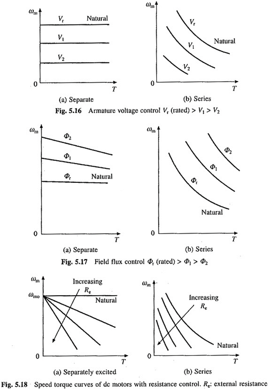
In a separately excited motor, flux is controlled by varying voltage across field winding and in a series motor it is controlled either by varying number of turns in the field winding or connecting a diverter resistance across the field winding.
In armature resistance control, speed is varied by wasting power in external resistors that are connected in series with the armature. Since it is an inefficient method of Speed Control of DC Motor Drives, it was used in intermittent load applications where the duration of low speed operation forms only a small proportion of total running time, for example in traction. It has, however, been replaced by armature voltage control in all these applications.
Induction motor drives
Induction Motors are the most commonly used motors in many applications. These are also called as Asynchronous Motors, because an induction motor always runs at a speed lower than synchronous speed. Synchronous speed means the speed of the rotating magnetic field in the stator.
There basically 2 types of induction motor depending upon the type of input supply - (i) Single phase induction motor and (ii) Three phase induction motor.
Or they can be divided according to type of rotor - (i) Squirrel cage motor and (ii) Slip ring motor or wound type
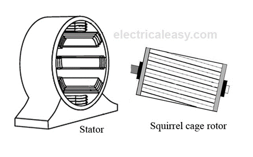
Basic Working Principle Of An Induction Motor
In a DC motor, supply is needed to be given for the stator winding as well as the rotor winding. But in an induction motor only the stator winding is fed with an AC supply.
§ Alternating flux is produced around the stator winding due to AC supply. This alternating flux revolves with synchronous speed. The revolving flux is called as "Rotating Magnetic Field" (RMF).
§ The relative speed between stator RMF and rotor conductors causes an induced emf in the rotor conductors, according to the Faraday's law of electromagnetic induction. The rotor conductors are short circuited, and hence rotor current is produced due to induced emf. That is why such motors are called as induction motors.
(This action is same as that occurs in transformers, hence induction motors can be called as rotating transformers.)
§ Now, induced current in rotor will also produce alternating flux around it. This rotor flux lags behind the stator flux. The direction of induced rotor current, according to Lenz's law, is such that it will tend to oppose the cause of its production.
§ As the cause of production of rotor current is the relative velocity between rotating stator flux and the rotor, the rotor will try to catch up with the stator RMF. Thus the rotor rotates in the same direction as that of stator flux to minimize the relative velocity. However, the rotor never succeeds in catching up the synchronous speed. This is the basic working principle of induction motor of either type, single phase of 3 phase.
Synchronous Speed:
The rotational speed of the rotating magnetic field is called as synchronous speed.
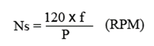
where, f = frequency of the spply
P = number of poles
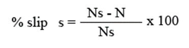
Slip:
Rotor tries to catch up the synchronous speed of the stator field, and hence it rotates. But in practice, rotor never succeeds in catching up. If rotor catches up the stator speed, there wont be any relative speed between the stator flux and the rotor, hence no induced rotor current and no torque production to maintain the rotation. However, this won't stop the motor, the rotor will slow down due to lost of torque, the torque will again be exerted due to relative speed. That is why the rotor rotates at speed which is always less the synchronous speed.
The difference between the synchronous speed (Ns) and actual speed (N) of the rotor is called as slip.
Permanent Magnet Motor Drives
Permanent Magnet BLDC machines can be categorized by the position of the rotor permanent magnet, the way in which the magnets are mounted on the rotor. The magnets can either be surface-mounted or interior-mounted.
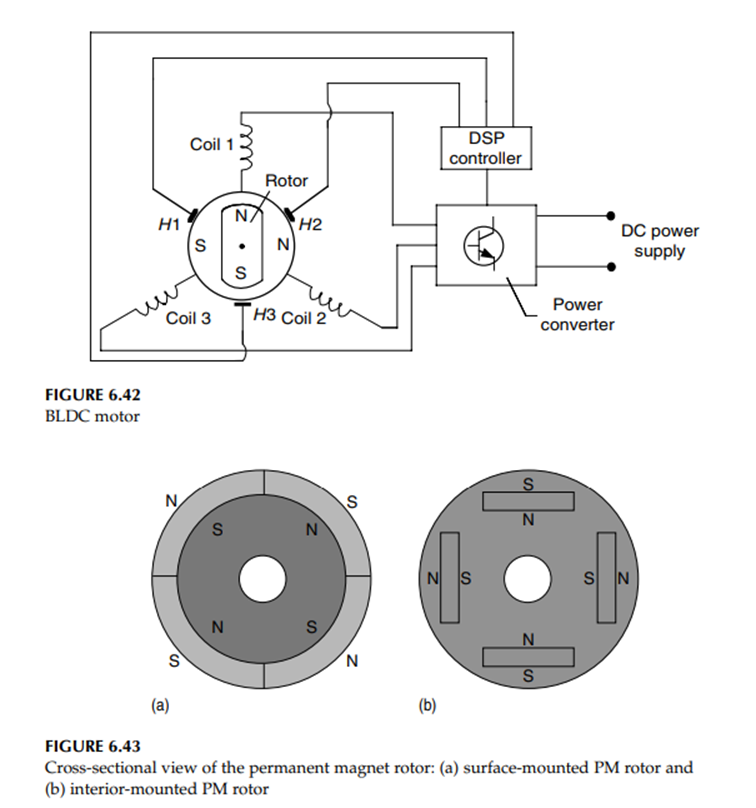
Figure 6.43(a) shows the surface-mounted permanent magnet rotor. Each permanent magnet is mounted on the surface of the rotor. It is easy to build, and specially skewed poles are easily magnetized on this surface-mounted type to minimize cogging torque. But there is a possibility that it will fly apart during high-speed operations.
Figure 6.43(b) shows the interior-mounted permanent magnet rotor. Each permanent magnet is mounted inside the rotor. It is not as common as the surface-mounted type but it is a good candidate for high-speed operations
In brushes motors, there are permanent magnets on the outside and a spinning armature which contains electromagnet is inside. These electromagnets create a magnetic field in the armature when the power is switched on and help to rotate the armature.
The brushes change the polarity of the pole to keep the rotation on of the armature. The basic working principle for the brushed DC motor and for brushless DC motor are same i.e. internal shaft position feedback.
Brushless DC motor has only two basic parts: rotor and the stator. The rotor is the rotating part and has rotor magnets whereas stator is the stationary part and contains stator windings. In BLDC permanent magnets are attached in the rotor and move the electromagnets to the stator. The high power transistors are used to activate electromagnets for the shaft turns. The controller performs power distribution by using a solid-state circuit.
Advantages of Brushless DC motor
High efficiency: BLDC motors are the most efficient of all electric motors. This is due to the use of permanent magnets for the excitation, which consume no power. The absence of a mechanical commutator and brushes means low mechanical friction losses and therefore higher efficiency
Compactness: The recent introduction of high-energy density magnets (rare-earth magnets) has allowed achieving very high flux densities in the BLDC motor. This makes it possible to achieve accordingly high torques, which in turns allows making the motor small and light.
Ease of control: The BLDC motor can be controlled as easily as a DC motor because the control variables are easily accessible and constant throughout the operation of the motor.
Ease of cooling: There is no current circulation in the rotor. Therefore, the rotor of a BLDC motor does not heat up. The only heat production is on the stator, which is easier to cool than the rotor because it is static and on the periphery of the motor.
Low maintenance, great longevity, and reliability: The absence of brushes and mechanical commutators suppresses the need for associated regular maintenance and suppresses the risk of failure associated with these elements. The longevity is therefore only a function of the winding insulation, bearings, and magnet life-length.
Low noise emissions: There is no noise associated with the commutation because it is electronic and not mechanical. The driving converter switching frequency is high enough so that the harmonics are not audible.
Limitations of Brushless DC motor
Cost: Rare-earth magnets are much more expensive than other magnets and result in an increased motor cost.
Limited constant power range: A large constant power range is crucial to achieving high vehicle efficiencies. The permanent magnet BLDC motor is incapable of achieving a maximum speed greater than twice the base speed.
Safety: Large rare-earth permanent magnets are dangerous during the construction of the motor because they may attract flying metallic objects toward them. In case of vehicle wreck, if the wheel is spinning freely, the motor is still excited by its magnets and high voltage is present at the motor terminals that can possibly endanger the passengers or rescuers.
Magnet demagnetization: Magnets can be demagnetized by large opposing mmfs and high temperatures. The critical demagnetization force is different for each magnet material. Great care must be exercised when cooling the motor, especially if it is built compact.
High-speed capability: The surface-mounted permanent magnet motors cannot reach high speeds because of the limited mechanical strength of the assembly between the rotor yoke and the permanent magnets.
Inverter failures in BLDC motor drives: Because of the permanent magnets on the rotor, BLDC motors present major risks in case of short circuit failures of the inverter. Indeed, the rotating rotor is always energized and constantly induces an EMF in the short-circuited windings. A very large current circulates in those windings and an accordingly large torque tends to block the rotor. The dangers of blocking one or several wheels of a vehicle are non-negligible.
If the rear wheels are blocked while the front wheels are spinning, the vehicle will spin uncontrollably. If the front wheels are blocked, the driver has no directional control over the vehicle. If only one wheel is blocked, it will induce a yaw torque that will tend to spin the vehicle, which will be difficult to control. In addition to the dangers to the vehicle, it should be noted that the large current resulting from an inverter short circuit poses a risk of demagnetizing and destroying the permanent magnets.
Applications of Brushless DC motor
Brushless DC motors (BLDC) use for a wide variety of application requirements such as varying loads, constant loads and positioning applications in the fields of industrial control, automotive, aviation, automation systems, health care equipments etc.
- Computer hard drives and DVD/CD players
- Electric vehicles, hybrid vehicles, and electric bicycles
- Industrial robots, CNC machine tools, and simple belt driven systems
- Washing machines, compressors and dryers
- Fans, pumps and blowers.
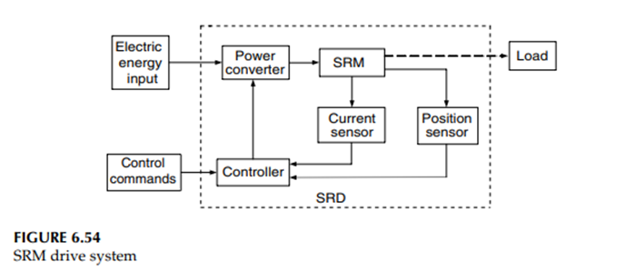
Switch Reluctance Motor Drive for Electric Vehicles
A switched reluctance motor produces torque by changing its magnetic reluctance as shown in Figure 1. Its stator has salient poles and includes windings identical to a brushless DC motor, but the rotor is made of steel cut into salient poles without magnets or windings. The power is supplied to its stator windings instead of the rotor, unlike the standard brushed DC motors.
SRM works by alternating currents in the stator when the magnetic field developed by stator and rotor changes. To prevent a condition where both rotor and stator poles align up together and no torque is produced, switched reluctance motors have fewer rotor poles than the stator.
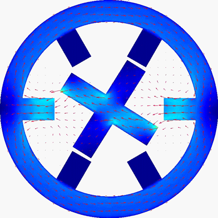
Figure 1: Structure of a switched reluctance motor .
The magnetic circuit developed between rotor and stator has high reluctance when they both are out of alignment. At this time, the stator pole pairs get energized, and the rotor tries to get in line with the powered stator poles, which decreases the magnetic reluctance.
This ability of rotor to reach the minimum point of reluctance produces a torque, known as reluctance torque. Excitation of the stator poles must be accurately timed to make sure that it happens only when the rotor is trying to be aligned with the excited pole. For this purpose, SRM may need positive feedback from Hall effect sensors or encoders to control the excitation of stator based on an accurate rotor position.
Configuration and control of Drives.
Electrical drives have become the most essential equipment now days in the electrical motors and other rotating machines. We know that electrical drives mainly accomplishes three kinds of work,
- Starting
- Speed control
- Braking
It can be said that the electrical drives enable us to control the motor in every aspect. But control of electrical drives is also necessary because all the functions accomplished by the drives are mainly transient operations i.e the change in terminal voltage, current, etc are huge which may damage the motor temporarily or permanently.
That’s why the need of controlling the drives rises and there are various methods and equipment’s to control different parameters of the drives
Closed Loop Control of Drives
In a control system, there are two types of systems, one is open loop and the other is closed loop control system. In open loop control systemthe output has no effect on the input, i.e the controlling phenomenon is independent of the output, on the other hand closed loop control systemis much more advanced and scientific, here the output is fed back to the input terminal which determines the amount of input to the system, for example if the output is more than predetermined value the input is reduced and vice-versa. In electrical drives feedback loops or closed loop control satisfy the following requirements.
- Protection
- Enhancement of speed of response
- To improve steady-state accuracy
In the following discussions, we will see through different closed loop configurations which are used in electrical drivesirrespective of the type of supply they are fed, i.e DC or AC.
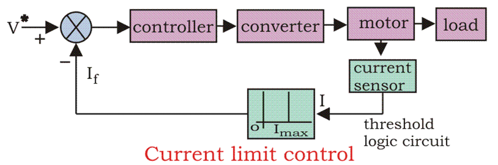
Current Limit Control
During the starting, we know if precautionary measures are not taken there is a chance of huge current flow through the motor circuit. To limit the current and sense the current fed to the motor, current limit controller is installed.
The feedback loop does not effect the normal operation of the drive but if the current exceeds the predetermined safe limit, the feedback loop activates and the current is brought down below the safe limit. Once the current is brought down below the safe limit the feedback loop again deactivates and in this way the control of current takes place.
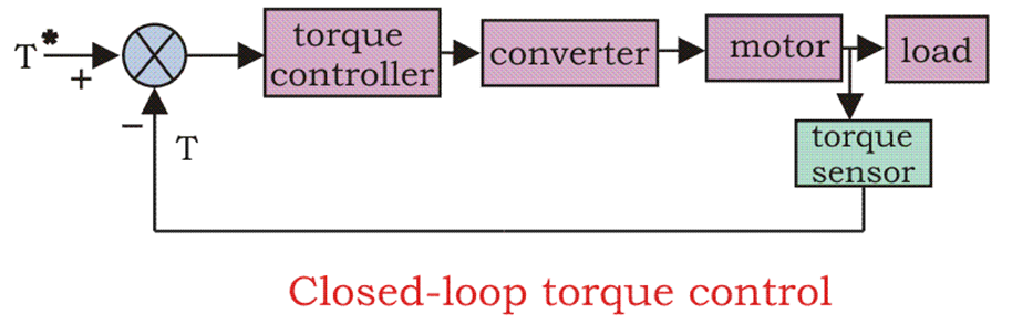
Closed Loop Torque Control
This type of torque controller is seen mainly in battery operated vehicles like cars, trains etc. the accelerator present in the vehicles is pressed by the driver to set the reference torque T. The actual torque T follows the T* which is controlled by the driver via accelerator.
Closed Loop Speed Control
Speed control loops are perhaps the most widely used feedback loops for drives. If we first see the block diagram of this loop then it will be a lot easier for us to understand.
We can see from the diagram that there are two control loops, which can be said as an inner loop and outer loop. The inner current control loop limits the converter and motor current or motor torque below the safe limit.
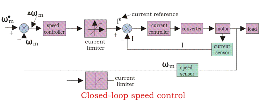
Now we can understand the function of the control loop and drive by practical examples. Suppose the reference speed Wm* increases and there is a positive error ΔWm, which indicates that the speed is needed to be increased.
Now the inner loop increases the current keeping it under maximum allowable current. And then the driver accelerates, when the speed reaches the desired speed then the motor torque is equal to the load torque and there is a decrease in the reference speed Wm which indicates that there is no need of any more acceleration but there must be deceleration, and braking is done by the speed controller at maximum allowable current.
So, we can say that during speed controlling the function transfers from motoring to braking and from braking to motoring continuously for the smooth operation and running of the motor.

