Electric Vehicle 5th Module
Design of Electric and Hybrid Electric Vehicles:
Series Hybrid Electric Drive Train Design:
The concept of a series hybrid electric drive train was developed from the electric vehicle drive train, electric vehicles, compared with conventional gasoline or diesel-fueled vehicles, have the advantages of zero mobile pollutant emissions, multienergy sources, and high efficiency.
However, electric vehicles using present technologies have some disadvantages: a limited drive range due to the shortage of energy storage in the on-board batteries, limited payload and volume capacity due to heavy and bulky batteries, and a longer battery charging time. The initial objective of developing a series hybrid electric vehicle (S-HEV) was aimed at extending the drive range by adding an engine/alternator system to charge the batteries on-board
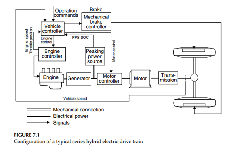
A typical series hybrid electric drive train configuration is shown in Figure 7.1. The vehicle is propelled by a traction motor. The traction motor is powered by a battery pack and/or an engine/generator unit.
The engine/generator unit either helps the batteries to power the traction motor when load power demand is large or charges the batteries when load power demand is small. The motor controller is to control the traction motor to produce the power required by the vehicle. Vehicle performance (acceleration, gradeability, and maximum speed) is completely determined by the size and characteristics of the traction motor drive.
The determination of the size of the motor drive and gears of transmission is the same as in the electric vehicle design. However, the drive train control is essentially different from the pure electric drive train due to the involvement of an additional engine/generator unit. We focus on the design of the engine/alternator system, operation control strategy, and battery size design. Also, the term “peak power source” will replace “battery pack,” because, in HEVs, the major function of batteries is to supply peaking power. They can be replaced with other kinds of sources such as ultracapacitors and flywheels.
Operating patterns
In series hybrid electric drive trains, the engine/generator system is mechanically decoupled from the driven wheels as shown in Figure 7.1
The speed and torque of the engine are independent of vehicle speed and traction torque demand, and can be controlled at any operating point on its speed–torque plane.3,4 Generally, the engine should be controlled in such a way that it always operates in its optimal operation region, where fuel consumption and emissions of the engine are minimized (see Figure 7.2). Due to the mechanical decoupling of the engine from the drive wheels, this optimal engine operation is realizable. However, it heavily depends on the operating modes and control strategies of the drive train
The drive train has several operating modes, which can be used selectively according to the driving condition and desire of the driver. These operating modes are:
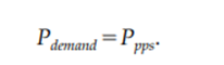
1. Hybrid traction mode: When a large amount of power is demanded, that is, the driver depresses the accelerator pedal deeply, both engine/generator and peaking power source (PPS) supply their powers to the electric motor drive. In this case, the engine should be controlled to operate in its optimal region for efficiency and emission reasons as shown in Figure 7.2. The PPS supplies the additional power to meet the traction power demand. This operation mode can be expressed as
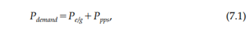
where Pdemand is the power demanded by the driver, Pe/g is the engine/ generator power, and Ppps is the PPS power.
2. Peak Power Source-Alone Traction Mode: In this operating mode, the peak power source alone supplies its power to meet the power demand, that is,
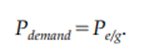
3. Engine/Generator-Alone Traction Mode: In this operating mode, the engine/generator alone supplies its power to meet the power demand, that is,
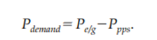
4. PPS Charging from the Engine/Generator: When the energy in the PPS decreases to a bottom line, the PPS must be charged. This can be done by regenerative braking or by the engine/generator. Usually, engine/generator charging is needed, since regenerative braking charging is insufficient. In this case, the engine power is divided into two parts: one is used to propel the vehicle and the other is used to charge the PPS. That is
5. Regenerative Braking Mode: When the vehicle is braking, the traction motor can be used as a generator, converting part of the kinetic energy of the vehicle mass into electric energy to charge the PPS.
Control strategies
A control strategy is a control rule that is preset in the vehicle controller and commands the operating of each component. The vehicle controller receives the operation commands from the driver and the feedback from the drive train and all the components, and then makes the decisions to use proper operation modes.
In practice, there are a number of control strategies that can be used in a drive train for vehicles with different mission requirements, two typical control strategies are (1) maximum state-of-charge of peaking power source (Max. SOC-of-PPS) and (2) engine turn-on and turnoff (engine-on–off) control strategies.
Max. SOC-of-PPS Control Strategy
The target of this control strategy is to meet the power demand commanded by the driver and, at the same time, maintain the SOC of the PPS at its high level. This control strategy is considered to be the proper design for vehicles for which the performance relies heavily on the peak power source. This includes vehicles with frequent stop–go driving patterns, and military vehicles for which carrying out their mission is the most important.
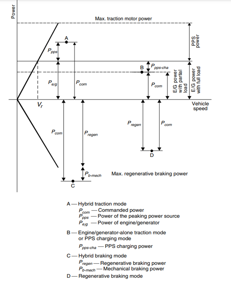
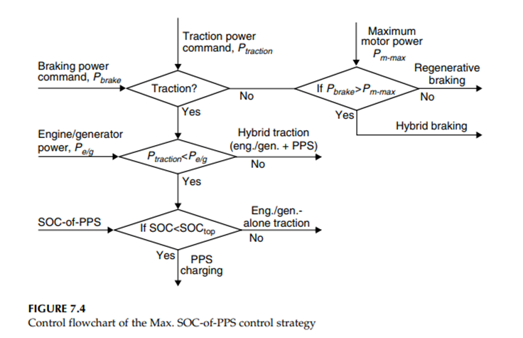
A high SOC level will guarantee the high performance of the vehicles at any time. The Max. SOC-of-PPS control strategy is depicted in Figure 7.3, in which points A, B, C, and D represent the power demands that the driver commands in either traction mode or braking mode.
Point A represents the commanded traction power that is greater than the power that the engine/generator can produce. In this case, the PPS must produce its power to make up the power shortage of the engine/generator.
Point B represents the commanded power that is less than the power that the engine/generator produces when operating in its optimal operation region (refer to Figure 7.2). In this case, two operating modes may be used, depending on the SOC level of PPS. If the SOC of the PPS is below its top line, the PPS charging mode is applied — that is, the engine/generator is operated within its optimal operating region and part of its power goes to the traction motor to propel the vehicle and the other part goes to the PPS. On the other hand, if the SOC of the PPS has already reached its top line, the engine/generator traction mode alone is supplied, that is, the engine/generator is controlled to produce power equal to the demanded power, and the PPS is set at idle.
Point C represents the commanded braking power that is greater than the braking power that the motor can produce (maximum regenerative braking power). In this case, the hybrid braking mode is used, in which the electric motor produces its maximum braking power and the mechanical braking system produces the remaining braking power.
Point D represents the commanded braking power that is less than the maximum braking power that the motor can produce. In this case, only regenerative braking is used. The control flowchart of Max. SOC-of-PPS is illustrated in Figure 7.4.
Thermostat Control Strategy (Engine-On–Off)
The Max. SOC-of-PPS control strategy emphasizes maintaining the SOC of the PPS at a high level. However, in some driving conditions such as long time driving with a low load on a highway at constant speed, the PPS can be easily charged to its full level, and the engine/generator is forced to operate with a power output smaller than its optimum. Hence, the efficiency of the drive train is reduced.
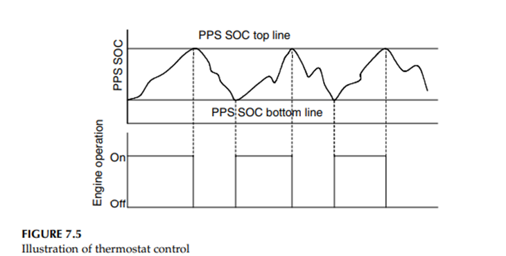
In this case, engine-on–off or thermostat control of the engine/generator would be appropriate. This control strategy is illustrated in Figure 7.5. The operation of the engine/generator is completely controlled by the SOC of the PPS. When the SOC of the PPS reaches its preset top line, the engine/generator is turned off and the vehicle is propelled only by the PPS.
On the other hand, when the SOC of the PPS reaches its bottom line, the engine/generator is turned on. The PPS gets its charging from the engine/generator. In this way, the engine can always be operated within its optimal deficiency region.
Sizing of major components
The major components in a series hybrid drive train include traction motor, engine/generator, and PPS. The design of the power ratings of these components is the first and most important step in the whole system design. In the design of these parameters, some design constraints must be considered,
Power rating of traction motor
The power rating of the electric motor drive in series HEV is completely determined by vehicle acceleration performance requirements, motor characteristics, and transmission characteristics.At the beginning of the design, the power rating of the motor drive can be estimated, according to the acceleration performance (time used to accelerate the vehicle from zero speed to a given speed), using the following equation
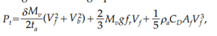
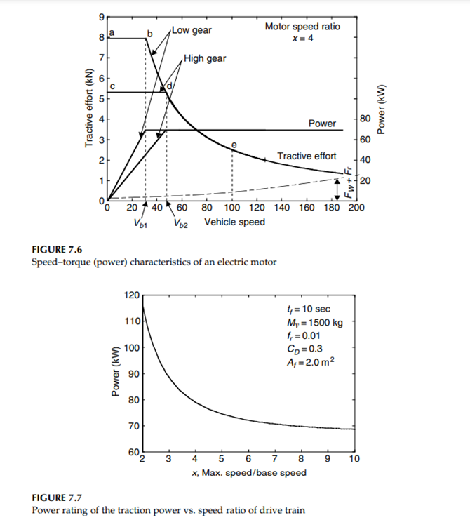
where Mv is the total vehicle mass in kg, tf is the expected acceleration time in sec, Vbis the vehicle speed in m/s, corresponding to the motor-based speed (see Figure 7.6), Vf is the final speed of the vehicle accelerating in m/s, g is gravity acceleration in 9.80 m/s2 , fr is the tire rolling resistance coefficient, ρa is the air density in 1.202 kg/m3 , Af is the front area of the vehicle in m2 , and CDis the aerodynamic drag coefficient.
The first term in equation (7.5) represents the power used to accelerate the vehicle mass, and the second and third terms represent the average power for overcoming the tire rolling resistance and aerodynamic drag.
Figure 7.6 shows the tractive effort and traction power vs. vehicle speed with a two-gear transmission. During acceleration, starting from low gear, the tractive effort follows the trace of a–b–d–e and Vb=Vb1. However, when a single-gear transmission is used, that is, only when a high gear is available, the tractive effort follows the trace of c–d–e and Vb=Vb2.
Figure 7.7 shows an example of the power rating of motor vs. speed ratio, which is defined as the ratio of maximum speed to the base speed as shown in Figure 7.6.
It should be noted that the rated motor power determined by equation (7.5) is only an estimate for meeting the acceleration performance. In order to accurately determine the rated motor power, verification would be necessary
The calculation of vehicle performance, such as acceleration time, acceleration distance, and gradeability, is exactly the same as that of a pure electric vehicle
Power rating of engine/generator
In the design of the engine/generator, two driving conditions should be considered: driving for a long time with constant speed, such as highway driving between cities, and driving with a frequent stop–go driving pattern, such as driving in cities.
With the former driving pattern (long time at a constant speed), the engine/generator and drive train should not rely on the PPS to support the operation at a high speed of, for example, 130 km/h or 80 mph. The engine/generator should be able to produce sufficient power to support this speed.
For a frequent stop–go driving pattern, the engine/generator should produce sufficient power to maintain the energy storage of the PPS at a certain level, so that enough power can be drawn to support vehicle acceleration. As mentioned above, the energy consumption in the PPS is closely related to the control strategy
When the vehicle is driving in a stop-and-go pattern in urban areas, the power that the engine/generator produces should be equal to or slightly greater than the average load power in order to maintain balanced PPS energy storage.

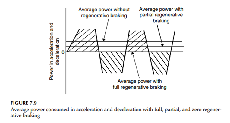
The first term in equation (7.8) is the average power that is consumed to overcome the tire rolling resistance and aerodynamic drag. The second term is the average power consumed in acceleration and deceleration.
When the vehicle has the ability to recover all of the kinetic energy of the vehicle, the average power consumed in acceleration and deceleration is zero. Otherwise, it will be greater than zero, as shown in Figure 7.9. In the design of an engine/generator system, the power capability should be greater than, or at least not less than, the power that is needed to support the vehicle driving at a constant speed (highway driving) and at average power when driving in urban areas
Design of PPS
The PPS must be capable of delivering sufficient power to the traction motor at any time. At the same time, the PPS must store sufficient energy to avoid failure of power delivery due to too-deep discharging
(i) Power Capacity of PPS To fully utilize the electric motor power capacity, the total power of the engine/generator and PPS should be greater than, or at least equal to, the rated maximum power of the electric motor. Thus, the power capacity of the PPS can be expressed as

where Pm,max is the maximum rated power of the motor, ηm is the efficiency of the motor, and Pe/gis the power of the engine/generator system.
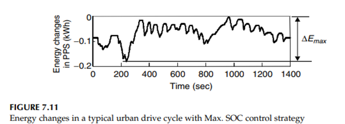
(ii) Energy Capacity of PPS In some driving conditions, a frequent accelerating/decelerating driving pattern would result in a low SOC in the PPS, thus losing its delivery power. In order to properly determine the energy capacity of the PPS, the energy changes in the PPS in some typical drive cycles must be known. The energy changes in the PPS can be expressed as
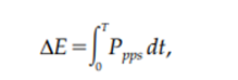
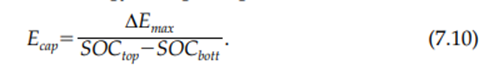
where Ppps is the power of the PPS. Positive Pppsrepresents charging power, and negative Ppps represents discharging power. Figure 7.11 shows an example in which the energy changes in the peaking power vary with driving time. Figure 7.11 also shows the maximum amount of energy changes, ∆Emax, in the whole drive cycle, if the SOC of the PPS is allowed in the operating range between SOCtop and SOCbott. The whole energy capacity of the peaking power can be calculated using equation (7.10). The operating range of PPS SOC depends upon the operating characteristics of the PPS.
Parallel Hybrid Electric Drive Train Design:
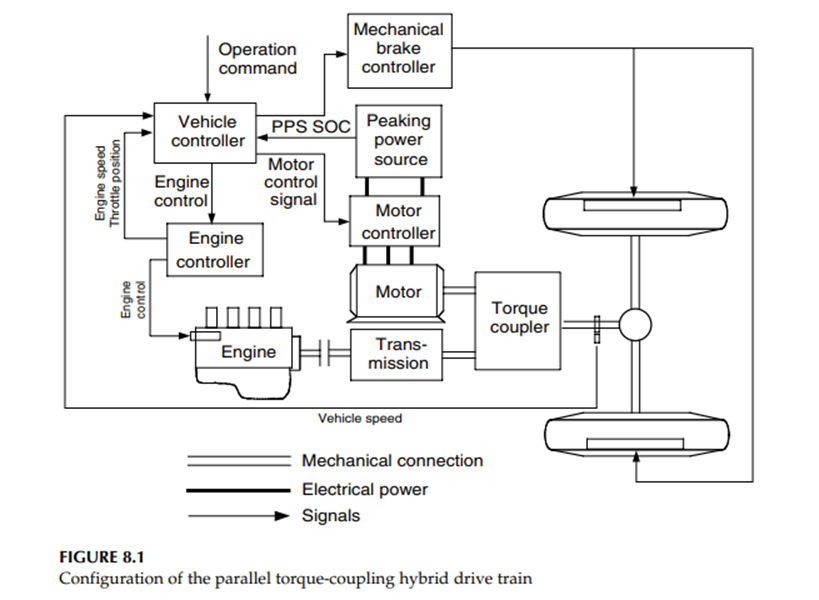
Unlike the series hybrid drive train, the parallel hybrid drive train has features that allow both the engine and traction motor to supply their mechanical power in parallel directly to the driven wheels. The major advantages of parallel configuration over a series configuration are
(1) generator is not required,
(2) the traction motor is smaller, and
(3) multiconversion of the power from the engine to the driven wheels is not necessary.
Hence, the overall efficiency can be higher.However, the control of the parallel hybrid drive train is more complex than that of a series hybrid drive train, due to the mechanical coupling between the engine and the driven wheels. There are several possibilities for configurations in a parallel hybrid drive train.
But the design methodology for one particular configuration may be not applicable to other configurations and the design result for a particular configuration may be applicable for only a given operation environment and mission requirement.
The base load is much lower than the peaking load in normal urban and highway driving,. This suggests that the engine power rating is lower than the electrical traction power rating. Due to the better torque–speed characteristics of the traction motor compared to the engine, the single-gear transmission for the traction motor might be the proper option.
Thus, will focus on the design of the drive train as shown in Figure 8.1.
The design objectives are:
1. To satisfy the performance requirements (gradeability, acceleration, and maximum cruising speed)
2. To achieve high overall efficiency
3. To maintain the battery state-of-charge (SOC) at reasonable levels in the whole drive cycle without charging from outside the vehicle
4. To recover the brake energy
Control strategies of parallel hybrid drive train
Maximum State-of-Charge of Peaking Power Source (Max. SOC-ofPPS) Control Strategy
When a vehicle is operating in a stop-and-go driving pattern, the PPS must deliver its power to the drive train frequently. Consequently, the PPS tends to be discharged quickly. In this case, maintaining a high SOC in the PPS is necessary to ensure vehicle performance. Thus, the maximum SOC of the PPS control strategy may be the proper option.2 The maximum control strategy can be explained by Figure 8.3.
In this figure, the maximum power curves for hybrid traction (engine plus electric motor), engine-alone traction, electric motor-alone traction, and regenerative braking are plotted against vehicle speed. Power demands in different conditions are also plotted, represented by points A, B, C, and D
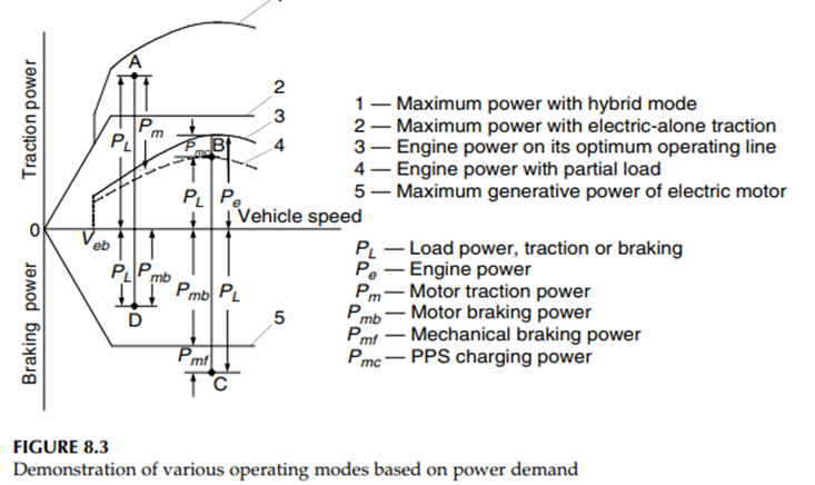
The operation modes of the drive train are explained below:
Motor-alone propelling mode:The vehicle speed is less than a preset value Veb, which is considered to be the bottom line of the vehicle speed below which the engine cannot operate steadily. In this case, the electric motor alone delivers its power to the driven wheels, while the engine is shut down or idling. The engine power, electric traction power, and the PPS discharge power can be written as

where Pe is the engine power output, PLis the load power demand on the drive wheels, ηt,m is the transmission efficiency from the motor to the driven wheels, Pm is the power output of the electric motor, Ppps-d is the PPS discharge power, and ηm is the motor efficiency
Hybrid propelling mode: The load power demand, represented by point A in Figure 8.3, is greater than what the engine can produce, both the engine and electric motor must deliver their power to the driven wheels at the same time. This is called hybrid propelling mode.
In this case, the engine operation is set on its optimum operation line by controlling the engine throttle to produce power Pe. The remaining power demand is supplied by the electric motor. The motor power output and PPS discharge power are

where ηt,e is the transmission efficiency from the engine to the drive wheels.
Engine-alone propelling mode: When the load power demand (represented by point B in Figure 8.3) is less than the power that the engine can produce while operating on its optimum operation line, and the PPS SOC has reached its top line, the engine-alone propelling mode is used.
In this case, the electric system is shut down, and the engine is operated to supply the power that meets the load power demand. The power output curve of the engine with a partial load is represented by the dashed line in Figure 8.3. The engine power, electric power, and battery power can be expressed by

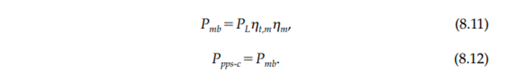
Regenerative-alone brake mode: When the vehicle experiences braking and the demanded braking power is less than the maximum regenerative braking power that the electric system can supply (as shown in Figure 8.3 by point D), the electric motor is controlled to function as a generator to produce a braking power that equals the commanded braking power.
In this case, the engine is shut down or set idling. The motor power output and PPS charge power are
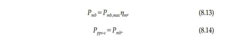
Hybrid braking mode: When the demanded braking power is greater than the maximum regenerative braking power that the electric system can supply (as shown in Figure 8.3 by point C), the mechanical brake must be applied. In this case, the electric motor should be controlled to produce its maximum regenerative braking power, and the mechanical brake system should handle the remaining portion. The motor output power, battery charging power, and mechanical braking power are
Engine Turn-On and Turn-Off (Engine-On–Off) Control
Strategy Similar to that used in a series hybrid drive train, the engine turn-on and turn-off control strategy may be used in some operation conditions with low speed and low acceleration.
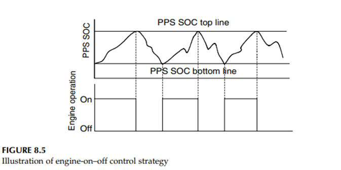
In an engine-on–off control strategy, the operation of the engine is controlled by the SOC of PPS, as shown in Figure 8.5.
In the engine-on period, the control is Max. SOC-of-PPS strategy. When the SOC of the PPS reaches its top line, the engine is turned off and the vehicle is propelled only by the electric motor. When the SOC of the PPS reaches its bottom line, the engine is turned on and the control again goes into Max. SOC-of-PPS.
Design of engine power capacity
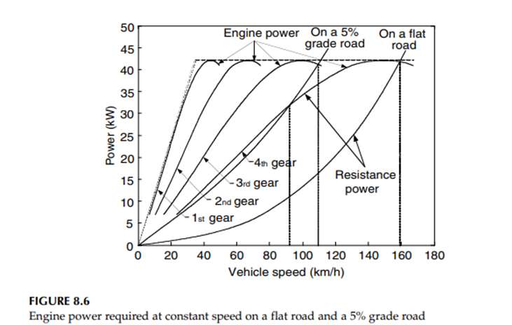
The engine should be able to supply sufficient power to support the vehicle operation at normal constant speeds both on a flat and a mild grade road without the help of the PPS. At the same time, the engine should be able to produce an average power that is larger than the average load power when the vehicle operates with a stop-and-go operating pattern
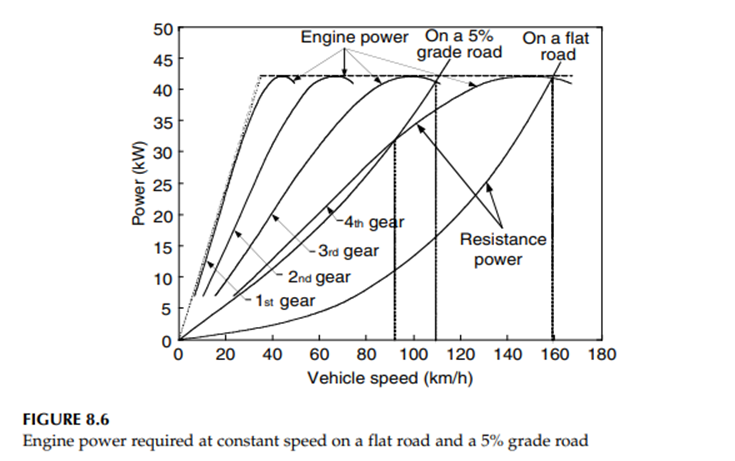
Figure 8.6 shows the load powers of a 1500 kg example passenger car, along with vehicle speed, on a flat road and a road with 5% grade. It is seen that on a flat road, a speed of 160 km/h (100 mph) needs a power of 42 kW.
For a comprehensive analysis, the power curves of a 42 kW engine with a multigear transmission are also plotted in Figure 8.6. From Figure 8.6, it can also be seen that on a 5% grade road, the vehicle can reach a maximum speed of about 92 and 110 km/h with the fourth gear and third gear, respectively. The above-designed engine power should be evaluated so that it meets the average power requirement while driving in a stop-and-go pattern. . In a drive cycle, the average load power of a vehicle can be calculated by

The average power varies with the degree of regenerative braking. The two extreme cases are the full and zero regenerative braking cases. Full regenerative braking recovers all the energy consumed in braking and the average power is calculated by (8.16). However, when the vehicle has no regenerative braking, the average power is larger than that with full regenerative braking, which can be calculated from (8.16) in such a way that when the instantaneous power is less than zero, it is given a zero.
Design of electric motor drive capacity
In HEV, the major function of the electric motor is to supply peak power to the drive train. In the motor power design, acceleration performance and peak load power in typical drive cycles are the major concerns.
It is difficult to directly design the motor power from the acceleration performance specified. It is necessary to make a good estimate based on specified acceleration requirements, and then make a final design through accurate simulation.
As an initial estimate, one can make the assumption that the steady-state load (rolling resistance and aerodynamic drag) is handled by the engine and the dynamic load (inertial load in acceleration) is handled by the motor. With this assumption, acceleration is directly related to the torque output of an electric motor by

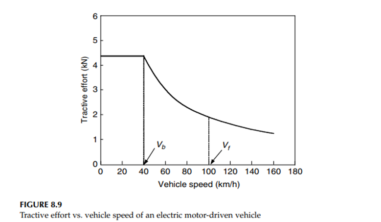
where Tm is the motor torque and δm is the mass factor associated with the electric motor (refer to Chapter 2). Using the output characteristics of the electric motor shown in Figure 8.5, and a specified acceleration time, ta, from zero speed to final high speed, Vf,, the motor power rating is expressed as
For a 1500 kg passenger car with a maximum speed of 160 km/h, a base speed of 50 km/h, a final acceleration speed of 100 km/h, acceleration time ta10 sec, and δm1.04, the power rating of the electric motor is 74 kW (Figure 8.9).
Transmission design
Since the electric motor supplies the peak power and has high torque at low speed, single-gear transmission between the electric motor and the driven wheels can produce sufficient torque for hill climbing and acceleration (refer to Figure 8.11). However, a multigear transmission between the engine and driven wheels can indeed enhance the vehicle performance.
The use of multigear transmission, as shown in Figure 8.6, can effectively increase the remaining power of the engine. Consequently, the vehicle performance (acceleration and gradeability) can be improved. On the other hand, the energy storage can be charged with the large power of the engine.
The vehicle fuel economy can also be improved, since the use of proper gears of the multigear transmission allows the engine to operate closer to its optimal speed region. Furthermore, the large remaining power of the engine can quickly charge the energy storage from low SOC to high SOC
However, multigear transmission is much more complex, heavier, and larger than single-gear transmission. Moreover, it also needs a complicated gear shifting control. Thus, in the design of parallel HEV, some trade-offs must be made.
Energy storage design
The energy storage design mainly includes the design for the power and energy capacity. The power capacity design is somewhat straightforward. The terminal power of the energy storage must be greater than the input electric power of the electric motor, that is,
where Pmand ηm are the motor power rating and efficiency
The energy capacity design of the energy storage is closely associated with the energy consumption in various driving patterns — mainly the full load acceleration and in typical drive cycles.
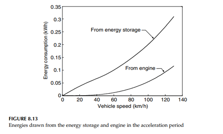
During the acceleration period, the energies drawn from energy storage and the engine can be calculated along with the calculation of the acceleration time and distance by

where Es and Eeng are the energy drawn from the energy storage and the engine, respectively, and Pm and Peare the powers drawn from the motor and engine, respectively. Figure 8.13 shows the energies drawn from the energy storage and the engine in the period of acceleration along the vehicle speed for the example passenger car.
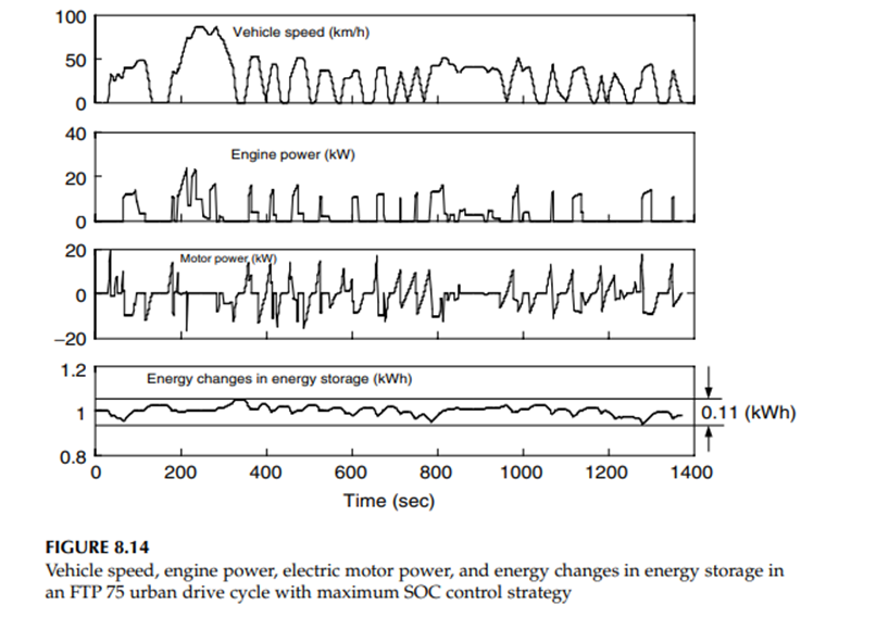
At an end speed of 120 km/h, about 0.3 kWh energy is drawn from the energy storage. The energy capacity of the energy storage must also meet the requirement while driving in a stop-and-go pattern in typical drive cycles. The energy changes of the energy storage can be obtained by

where Psc and Psd are the charging and discharging power of the energy storage. With a given control strategy, the charging and discharging power of the energy storage can be obtained by drive train simulation.
Figure 8.14 shows the simulation results of the example passenger car in an FTP 75 urban drive cycle with maximum SOC control strategy. It can be seen that the maximum energy change in the energy storage is about 0.11 kWh, which is less than that in full load acceleration (0.3 kWh).
Thus, the energy consumption in fuel load acceleration determines the energy capacity of the energy storage. Actually, not all the energy stored in the energy storage can be fully used to deliver sufficient power to the drive train.
In the case of batteries used as the energy storage, low SOC will limit their power output, and will at the same time lead to a low efficiency, due to an increase of internal resistance. In the case of ultracapacitors used as the energy storage, low SOC will result in low terminal voltage that will affect the performance of the traction motor.