
Industrial Robotics 2nd Module
Robot Anatomy
Robot Anatomy is concerned with the physical construction of the body, arm, and wrist of the machine. Most robots used in plants today are mounted on a base which is fastened to the floor. The body is attached to the base and the arm assembly is attached to the body. At the end of the arm is the wrist.
The wrist consists of a number of components that allow it to be oriented in a variety of positions. Relative movements between the various components of body, arm, and wrist are provided by a series of joints. These joint movements usually involve either rotating or sliding motions.
The body arm and wrist assembly is called the manipulator. Attached to the robot’s wrist is a hand or a tool called the “end effector”. The end effector is not considered as part of the robot’s anatomy. The arm and body joints of the manipulator are used to position the end effector, and the wrist joints of the manipulator are used to orient the end effector.
Four Common Robot Configurations
1. Polar Configuration (Spherical)
2. Cylindrical Configuration
3. Cartesian coordinate Configuration
4. Jointed arm configuration
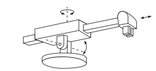
Polar Configuration
· It uses a arm that can be raised or lowered about a horizontal pivot
· The pivot is mounted on a rotating base.
· The various joints provide the robot with capability to movie its arm within a spherical space and hence it is also called as “Spherical Coordinate Robot”
· It has one linear and two rotary motions.
Advantages
· Larger work envelope than the rectilinear or cylindrical configuration
· Vertical structure conserves less space
Disadvantages
· Repeatability and accuracy are also lower in the direction of rotary motion
· Requires more sophisticated control system
Applications
· Die casting
· Forging
· Glass handling
· Injection Molding
· Stacking and unstacking
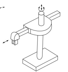
Cylindrical Configuration
· Cylindrical configuration uses a vertical column and a slide that can be moved up or down along the column.
· The robot arm is attached to the slide so that it can be moved with respect to the column.
· By rotating the column, the robot is capable of achieving a work space that approximates a cylinder
Advantages
· It has higher load carrying capacity
· It provides high rigidity to the manipulator
· It is generally suitable for pick and place applications
Disadvantages
· It requires more floor space
· It has a reduced mechanical rigidity because robots with a rotary axis must overcome the inertial of the object when rotating
Applications
· Conveyer pallet transfers
· Machine tool loading
· Forging applications
· Packing operation
· Precision small assembly
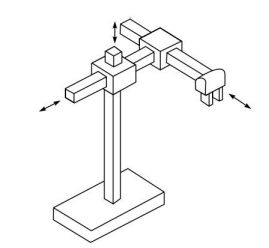
Cartesian coordinate robot
· Cartesian or rectangular coordinate configuration is constructed by three perpendicular slides, giving only linear motions along the three principal axes.
· It consists of three prismatic joints.
· The endpoints of the arm are capable of operating in a cuboidal space
· The cartesian arm gives high precision and is easy to program
· These robots are also called XYZ robots because they are equipped with three rotary joints to assemble XYZ axes.
Advantages
· Highly Accurate and speed
· Fewer costs
· Simple operating procedures
· High payloads
Limitations
· Less work envelope
· Low dexterity
· Limited maniplability
Applications
· Pick and Place
· Material handling
· Loading
· Unloading
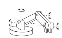
Jointed Arm Configuration
· Widely-used jointed arm configuration is similar to that of a human arm.
· It comprises two straight links representing the human forearm and upper arm and two rotary joints representing the elbow and shoulder joints, which are mounted on a vertical rotary table corresponding to the human waist joint.
· As a result, it can be controlled at any adjustments in the workspace.
Advantages
· Increased flexibility,
· Huge work volume and
· Quick operation.
Disadvantages
· Very expensive
· Difficult operating procedures
· Plenty of components
Applications
· Spray Painting
· Spot Welding
· Arc Welding
Robot Motions
Industrial robots are designed to perform productive work such as pick and place, welding, assembly etc. The work is accomplished by enabling the robot to move its body, arm and wrist through a series of motions and positions. Attached to the wrist is the end effector which is used by the robot to perform a specific work task. The individual joint motions associated with the performance of a task are referred to by the term degrees of freedom (DOF) and a typical industrial robot is equipped with four to six degrees of freedom. The opening and closing of gripper is not considered degree of freedom.
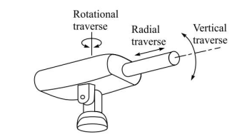
For robots of polar, cylindrical or jointed arm configuration, the three degrees of freedom associated with the arm and body motions are:
Vertical traverse: This is the capacity to move the wrist up or down to provide the desired vertical attitude
Radial Traverse: This involves the extension or retraction (in or out movement) of the arm from the vertical centre of the robot
Rotational traverse: This is the rotation of the arm about the vertical axis.
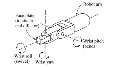
The wrist movement is designed to enable the robot to orient the end effector properly with respect to the task being performed. For example, the hand must be properly oriented to the work being performed such as welding, grasping etc. To solve this orientation problem, the wrist is normally provided with up to three degrees of freedom
1. Wrist roll: Also called wrist swivel, this involves rotation of the wrist mechanism about the arm axis
2. Wrist pitch: Given that the wrist roll is in its centre position, the pitch would involve the up or down rotation of the wrist. Wrist pitch is also sometimes called wrist bend
3. Wrist Yaw: Again given that the wrist swivel is the centre position of its range, wrist yaw would involve the right or left rotation of the wrist
Work Volume
Work volume is the term that refers to the space within which the robot can manipulate its wrist end. The convention of using the wrist end to define the robot’s work volume is adopted to avoid the complication of different sizes of end effectors that might be attached to the robot’s wrist.
The end effector is an addition to the basic robot and should not be counted as part of the robot’s working space. Also, the end effector attached to the wrist might not be capable of reaching certain points within the robot’s normal work volume because of the particular combination of joint limits of the arm.
The work volume is determined by the following physical characteristics of the robot:
- The robot’s physical configuration (type of joints, structure of links)
- The sizes of the body, arm, and wrist components
- The limits of the robot’s joint movements
Fig shows different work volume of different types of robots
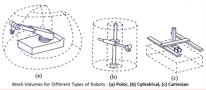
A polar robot has a work volume that is partial sphere
A cylindrical robot has a cylindrical work volume
A Cartesian robot has a work volume that is made of a rectangular shaped space
An anthropomorphic robot has a work volume made up of two or more spheres on the inside and one sphere on the outside.
Robot Drive System
The robot’s capacity to move its body, arm, and wrist is provided by the drive system used to power the robot. The drive system determines its speed of operation, load carrying capacity, and its dynamic performance.
To some extent, the drive system determines the kinds of applications that the robot can accomplish. In this and the following sections, we will discuss some of these technical features.
Types of Drive Systems
Commercially available industrial robots are powered by one of three types of drive systems. These three systems are:
- Hydraulic drive
- Electric drive
- Pneumatic drive
- Advanced actuators
Hydraulic drive and electric drive are the two main types of drives used on more sophisticated robots, while pneumatic drive is used for low load carrying capacity robots and in cases where oil and electricity cannot be used (fire hazard).
Hydraulic drive is generally associated with larger robots. The usual advantages of the hydraulic drive system are that it provides the robot with greater speed and strength.
The disadvantages of the hydraulic drive system are that it typically adds to the floor space required by the robot, and that a hydraulic system is inclined to leak oil which is a nuisance.
Hydraulic drive systems can be designed to actuate either rotational joints or linear joints. Rotary vane actuators can be utilized to provide rotary motion, and hydraulic pistons can be used to accomplish linear motion.
Electric drive systems do not generally provide as much speed or power as hydraulic systems. However, the accuracy and repeatability of electric drive robots are usually better.
Consequently, electric robots tend to be smaller, requiring less floor space, and their applications tend toward more precise work such as assembly. Electric drive robots are actuated by dc stepping motors or dc servomotors.
These motors are ideally suited to the actuation of rotational joints through appropriate drive train and gear systems. Electric motors can also be used to actuate linear joints (e.g., telescoping arms) by means of pulley systems or other translational mechanisms.
The economics of the two types of drive systems are also a factor in the decision to utilize hydraulic drive on large robots and electric drive on smaller robots.
It turns out that the cost of an electric motor is much more proportional to its size, whereas the cost of a hydraulic drive system is somewhat less dependent on its size.
It should be noted that there is a trend in the design of industrial robots toward all electric drives, and away from hydraulic robots because of the disadvantages discussed above.
Pneumatic driveis generally reserved for smaller robots that possess fewer degrees of freedom (two- to four-joint motions). These robots are often limited to simple pick-and-place operations with fast cycles.
These drives have the added advantage of having compliance or ability to absorb some shock during contact with devices to provide translational movement of sliding joints. It can also be used to operate rotary actuators for rotational joints.
Control Systems
In order to operate, a robot must have a means of controlling its drive system to properly regulate its motions.
Four types of Robot Controls
Commercially available industrial robots can be classified into four categories according to their control system. The types of robot controls :
Limited sequence robots
Playback robots with point to point control
Playback robots with continuous path control
Intelligent robots
Limited Sequence Robots
Of the four categories, the limited sequence robotsrepresent the lowest level of control and intelligent robots are the most sophisticated.
Limited sequence robots do not use servo-control to indicate relative positions of the joints. Instead, they are controlled by setting limit switches and/or mechanical stops to establish the endpoints of travel for each of their joints.
Establishing the positions and sequence of these stops involves a mechanical set-up of the manipulator rather than robot programming in the usual sense of the term.
With this method of control, the individual joints can only be moved to their extreme limits of travel. This has the effect of severely limiting the number of distinct points that can be specified in a program for these robots.
The sequence in which the motion cycle is played out is defined by a pegboard or stepping switch or other sequencing device.
This device, which constitutes the robot controller, signals each of the particular actuators to operate in the proper succession. There is generally no feedback associated with a limited-sequence robot to indicate that the desired position has been achieved.
Any of the three drive systems can be used with this type of control system; however, pneumatic drive seems to be the type most commonly employed.
Applications for this type of robot generally involve simple motions, such as pick-and-place operations.
Playback robots with point-to-point control
Playback robots use a more sophisticated control unit in which a series of positions or motions are “taught” to the robot, recorded into memory, and then repeated by the robot under its own control.
The term “playback” is descriptive of this general mode of operation. The procedure of teaching and recording into memory is referred to as programming the robot.
Playback robots usually have some form of servo-control (e.g., closed loop feedback system) to ensure are the positions that have been taught.
Playback robots can be classified into two categories: point-to-point (PTP) robots and continuous-path (CP) robots. Point-to-point robots are capable of performing motion cycles that consist of a series of desired point locations and related actions.
The robot is taught each point, and these points are recorded into the robot’s control unit. During playback, the robot is controlled to move from one point to another in the proper sequence.
Point-to-point robots do not control the path taken by the robot to get from one point to the next. If the programmer wants to exercise a limited amount of control over the path followed, this must sequence of positions is quite adequate for many kinds of applications, including loading and unloading machines and spot welding.
Playback robots with continuous path control
Continuous-path robots are capable of performing motion cycles in which the path followed by the robot is controlled. This is usually accomplished by making the robot move through a series of closely spaced points which describe the desired path.
The individual points are defined by the control unit rather than the programmer. Straight line motion is a common form of continuous-path control for industrial robots.
The programmer specifies the starting point and the end point of the path, and the control unit calculates the sequence of individual points that permit the robot to follow a straight line trajectory.
Some robots have the capability to follow a smooth, curved path that has been defined by a programmer who manually moves the arm through the desired motion cycle.
To achieve continuous-path control to more than a limited extent requires that the controller unit be capable of storing a large number of individual point locations that define the compound curved path.
Today this usually involves the use of a digital computer (a microprocessor is typically used as the central processing unit for the computer) as the robot controller.
CP control is required for certain types of industrial applications such as spray coating and arc welding.
Intelligent robots
Intelligent robots constitute a growing class of industrial robot that possesses the capability not only to play back a programmed motion cycle but also to interact with its environment in a way that seems intelligent.
Invariably, the controller unit consists of a digital computer or similar device (programmable controller). Intelligent robots can alter their programmed cycle in response to conditions that occur in the workplace.
They can make logical decisions based on sensor data received from the operation. The robots in this class have the capacity to communicate during the work cycle with humans or computer based systems.
Intelligent robots are usually programmed using an English-like symbolic language, unlike a computer programming language.
Indeed, the kinds of applications that are performed by intelligent robots rely on the use of a high-level language to accomplish the complex and sophisticated activities that can be accomplished by these robots.
Typical applications for intelligent robots are assembly tasks, space applications, under sea, nuclear applications, defense applications, etc.
Intelligent robots have been made possible by the availability of cheap electronics, smaller and faster processors and smart materials-based actuators and sensors.
Precision of movement
A robot is expected to perform repeated tasks in a real world and hence its performance is ultimately measured by its ability to position and orient the end effector at the desired location a large number of times. We will define precision as a function of three features:
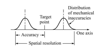
1. Spatial Resolution: The spatial resolution of a robot is the smallest increment of movement into which the robot can divide its work volume.
Spatial resolution depends on two factors: the system’s control resolution and the robot’s mechanical inaccuracies.
The control resolution is determined by the robot’s position control system and its feedback measurement system.
2. Accuracy: Accuracy refers to a robot’s ability to position its wrist end at a desired target point within the work volume.
The accuracy of a robot can be defined in terms of spatial resolution because the ability to achieve a given target point depends on how closely the robot can define the control increments for each of its joint motion
In the worst case, the desired point would be in the middle between two adjacent control increments. This relation shop is shown in fig
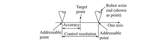
In fact, the mechanical inaccuracies would affect the ability to reach the target position, Accordingly we define the robot’s accuracy to be one-half of its spatial resolution as shown in fig below
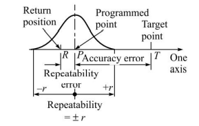
Repeatability
Repeatability is concerned with the robot’s ability to position its wrist or an end effector attached to its wrist at a point in space that had previously been taught to the robot.
Repeatability and accuracy refer to two different aspects of the robot’s precision. Accuracy relates to the robot’s capacity to be programmed to achieve a given target point. Repeatability refers to the robot’s ability to return to the programmed point when commanded to do so.
Compliance: The compliance of the robot manipulator refers to the displacemenet of the wrist end in response to a force or torque exerted against it.
A high compliance means that the wrist is displace by a large amount by a relative small force. The term springy is sometimes used to describe a robot with high compliance.
A low compliance means that the manipulator is relatively stiff and is not displaced by a significant amount
Robot manipulator compliance is a directional feature. That is, the compliance of the robot arm will be greater in certain directions than in other directions because of the mechanical construction of the arm.
Compliance is important because it reduces the robot’s precision of movement under load.
End effectors
In robotics, the term ‘end effector’ is used to describe the hand or tool that is attached to the robot’s wrist. The end effector represents the special tooling that permits the general purpose robot to perform a particular application. This special tooling must usually be designed specifically for the application.
End effectors can be divided into two categories: grippers and tools. Grippers would be utilised to grasp an object, usually the work part, and hold it during the robot work cycle. There are a variety of holding methods that can be used in addition to the obvious mechanical means of grasping the part between two or more more fingers.
These additional methods include the use of suction cups, magnets, hooks and scoops.
A tool would be used as an end effector in applications where the robot is required to perform some operation on the work part. These applications include spot welding arc welding spray painting etc.
In each case the particular tool is attached to the robot’s wrist to accomplish the application
With the recent need for holding micro and nano size parts for assembly, several new devices have been developed using smart actuators, PZT and ionic polymers etc
Robotic sensors
Sensors used in robotics can be divided into external sensors and internal sensors.
External sensors are used for interacting with the environment, while internal sensors are required to close the loop for feedback control.
A robot working in closed loop cannot work without internal sensors. A few examples of sensors are
(a) External Sensors: vision, force torque, proximity etc.
(b) Internal Sensors: position, velocity, acceleration
Sensors are not only required for working of the robot and interacting with environment, but also for safety and work cell control and monitoring
Among all the external sensors vision is the most versatile and can be used for several applications.
Vision systems can be used to locate objects for manipulation, measure their dimensions, detect intrusions in the work cell etc.
A robot has to communicate with other machines and devices and this also depends on several sensor information. Simple sensors are used to detect the presence of a part on a conveyer, completion of a task, forces or torques being applied in an assembly task etc.
Robot programming and work cell control
In its most basic form, a robot program can be defined as a path in space through which the manipulator is directed to move. This path also includes other actions such as controlling the end effector and receiving signals from sensors. The purpose of robot programming is to teach these actions to the robot.
There are various methods used for programming robots. The two basic categories of greatest commercial importance today are lead through programming and textual language programming.
Lead through programming consists of forcing the robot arm to move through the required motion sequence and recording the motions into the controller memory. Lead through methods are used to program playback robots.
In the case of point-to-point playback robots, the usual procedure is to use a control box (called a teach pendant) to drive the robot joints to each of the desired points in the workspace, and record the points into memory for subsequent playback.
The teach pendant is equipped with a series of switches and dials to control the robot’s movements during the teach procedure. Owing to its ease and convenience and the wide range of applications suited to it, this lead through method is the most common programming method for playback-type robots.
Continuous-path playback robots also use lead through programming. A teach pendant can be employed to teach the locations of the two points; and the robot controller then computes the trajectory to be followed in order to execute the complex motions.
For more complex motions (e.g., those encountered in spray painting operations), it is usually more convenient for the programmer to physically move the robot arm and end effector through the desired motion path and record the positions at closely spaced sampling intervals.
Textual programming methods use an English-like language to establish the logic and sequence of the work cycle. A computer terminal is used to input the program instructions into the controller but a teach pendant is also used to define the locations of the various points in the workspace.
The robot programming language names the points as symbols in the program and these symbols are subsequently defined by showing the robot their locations. In addition to identifying points in the workspace, the robot languages permit the use of calculations, more detailed logic flow, and subroutines in the programs, and greater corresponds largely to the so-called intelligent robots.
Some examples of the kinds of programming statements that would be found in the textual robot languages include the following sequence:
SPEED 35 IPS
MOVE P1
CLOSE 40 MM
WAIT 1 SEC
DEPART 60 MM
The series of commands tells the robot that its velocity at the wrist should be 35 in./sec. in the motions which follow. The MOVE statement indicates that the robot is to move its gripper to point P1 and close to an opening of 40 mm. It is directed to wait 1.0 sec. before departing from P1 by a distance of 60 mm above the point.
All of the current methods of programming require the participation of the robot in order to perform the programming function. With off-line programming, the entire program can be entered into a computer for later downloading to the robot.
Off-line programming would hasten the changeover from one robot work cycle to a new work cycle without a major time delay for reprogramming. Unfortunately, there are certain technical problems associated with off-line programming.
These problems are mainly concerned with defining the spatial locations of the positions to be used in the work cycle, and that is why the teach pendant is required in today’s textual robot languages.
In addition to the lead through and textual language programming methods, there is another form of programming for the low-technology-limited sequence robots. These robots are programmed by setting limit switches, mechanical stops, and other similar means to establish the endpoints of travel for each of the joints.
This is sometimes called mechanical programming; it really involves more of a manual setup procedure rather than a programming method. The work cycles for these kinds of robots generally consist of a limited number of simple motions (pick and place applications), for which this manual programming method is adequate.
Work cell controldeals with the program of coordinating the robot to operate with other equipment in the work cell. A robot cell usually consists of not only the robot, but also conveyors, machine tools, inspection devices, and possibly human operators.
Some of the activities in the robot work cell occur sequentially, while other activities occur simultaneously. A method of controlling and synchronizing these various activities is required, and that is the purpose of the work cell controller.
Work cell control is accomplished either by the robot controller or a separate small computer or programmable controller. During operation, the controller communicates signals to the equipment in the cell and receives signals from the equipment.
These signals are sometimes called interlocks. By communicating back and forth with the different components of the work cell, the various activities in the cell are accomplished in the proper sequence.
Robot Applications
Robot are employed in a wide assortment of applications in industry. Today, most of the applications are in manufacturing to move materials, parts, and tools of various types. Nonmanufacturing tasks include exploration of space, defense, and medical care.
At some time in the near future, a household robot may become a mass produced item, perhaps as commonplace as the automobile is today. Simple toy robot that can perform simple reprogrammable functions are already commonplace.
For the present, most industrial applications of robots can be divided into the following categories:
Material-handling and machine-loading and unloading applications – In these applications, the robot’s function is to move materials or parts from one location in the work cell to some other location.
Processing applications – This category includes spot welding, arc welding, spray painting, and other operations in which the function of the robot is to manipulate a tool to accomplish some manufacturing process in the work cell. Spot welding represents a particularly important application in the processing category.
Assembly and inspection – These are two separate operations which we include together in this category. Robotic assembly is a field in which the industry is showing great interest because of its economic potential.
Advanced applications – Rehabilitation, outer space, defense, pets, security, etc.

