Industrial Robotics 3rd Module
Basic control systems concepts and models
When studying a mechanical system, we are concerned with the response of the system to certain inputs. These inputs include commands to ‘drive the system components:
1. The input (or inputs) to the system
It is a signal from the external energy source applied to the control system to produce the desired output.
Or
It is the desired action that is capable of producing any response in a system.
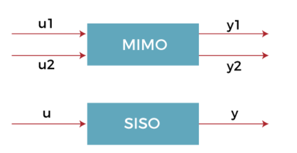
The common types of input used in the control system are SISO (Single Input Single Output) and MIMO (Multiple Input and Multiple Output). SISO means that the system produces single output for the single input, while MIMO produces multiple outputs for the multiple inputs. It is shown below:
2. The controller and actuating devices
The controller is the element of the system. It can also lie external to the system. The function of the controller is to control the plant or process. Every system accepts an input and defines the output after analyzing the nature of the input. The controller in the control system is a mechanism that reduces the difference between the actual value and desired value of the system. Here, the actual value signifies the real value, while desired value is the set-point or target value.
3. The plant (the mechanism or process being controlled)
The portion of the system that is to be controlled or regulated is known as plant of the process. In a control system, it is often referred to a transfer function, which specifies the relationship between the input and output of the system without feedback. It means that plant can be anything that has an input and provides the output.
The plant can have one or more output and inputs. The sensors are used to measure the plant's output, while actuators drive the plants inputs.
The diagram of the plant is shown below:

The input variable in a system is generally called reference input and the output is called as the controller output.
4. The output (the controlled variable)
It is an actual response of the applied input signal from the control system. The inputs are excited into the system and the outputs are the processed results of that inputs. The outputs are the results of either a small part of the process or the entire process.
5. Feedback elements (sensors)
Disturbances or feedback are a type of signal which adversely affects the output value of the control system. The disturbances or feedback can be internal or external. The internal disturbances or feedback that arise in the system itself and the external disturbances or feedback are generated outside the system. Such disturbances or feedback act as an extra input to the system and the normal input and further affect the system's output
Controllers
There are four basic control actions which are used singly or in combination to provide six common types of controller: on-off control, proportional control, derivative control and integral control. The six controller types are:
1. On-off
2. Proportional
3. Integral
4. Proportional-plus-integral (P-I)
5. Proportional-plus-derivative (P-D)
6. Proportional-plus-integral-plus-derivative (P-I-D)
each one of these controller types is best suited to certain applications
1. On-Off Control: In the on–off controller, the control element provides only two levels of control, full-on or full-off. An example of a common implementation of this type of controller is the household thermostat.
If the error which is present at the controller is e(t) and the control signal which is produced by the controller is m(t), then the on–off controller is represented by

In most on–off controllers either M1 or M2 is zero. The practical use of an on– off controller usually requires that the error must move through some range before switching actually takes place. This prevents the controller from oscillating at too high a frequency.
This range is referred to as the differential gap.
2. Proportional Control
In cases where a smoother control action is required a proportional controller may be used. Proportional control provides a control signal that is proportional to the error. Essentially, it acts as an amplifier with a gain Kp.
Its action is represented by

Using the differential operator notation introduced earlier the transfer function would be

3. Integral Control
In a controller employing an integral control action the control signal is changed at a rate proportional to the error signal. That is, if the error signal is large, the control signal increases rapidly, if it is small, the control signal increases slowly.
This may be represented by

Where Ki is the integrator gain. The corresponding transfer function is

Using 1/s as the operator for integration. If the error were to go to zero, the output of the controller would remain constant. This feature allows integral controllers to be used when there is some type of constant load on the system. Even if there is no error the controller would still maintain an output signal to counteract the load.
4. Proportional-plus-lntegral
Control Sometimes it is necessary to combine control actions. A proportional con troller is incapable of counteracting a load on the system without an error. An integral controller can provide zero error but usually provides slow response.
One way to overcome this is with the P-I controller. This is represented by

where Ti adjusts the integrator gain and Kp adjusts both the integrator and the proportional gain. The transfer function is

5. Proportional-plus-Derivative Control
Derivative control action provides a control signal proportional to the rate of change of the error signal. Since this would generate no output unless the error is changing, it is rarely used alone. The P-D controller is represented by

and the transfer function is

The effect of derivative control action is to anticipate changes in the error and provide a faster response to changes
6. Proportional-plus-Integral-plus-Derivative Control
Three of the control actions can be combined to form the P-I-D controller. The P-I-D controller can be represented by

and the transfer function is

P-I-D control is the most general control type and probably the most commonly used type of controller. It provides quick response, good control of system stability and low steady-state error.
As indicated previously, the computations associated with any of the above controllers are typically performed by microcomputers in a modern robot controller
Control system analysis
Analysis of a control system may be divided into two parts: transient response and steady-state response. The transient response of a system is the behavior of the system during the transition from some initial state to the final state. The steady-state response is the behaviour of the system as time approaches infinity.
Transient Response of Second-Order Systems
Second-order linear systems are frequently used in control systems analysis, even when it is known that the particular system of interest may be of higher order. Secondorder systems can often approximate complex physical systems with reasonable fidelity.
The damping ratio of a second order system can be defined as

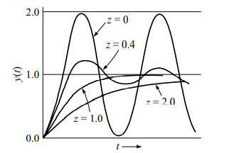
If the damping ratio is equal to zero then the system will oscillate continuously, if z < 1 but greater than zero then the system is underdamped, If z = 1 then the system is critically damped and if z > 1 the system is overdamped. Fig. 3.9 illustrates the transient response of a second-order system with different damping ratios to a unit step input. There are other parameters of interest in the transient response of a system. These are:
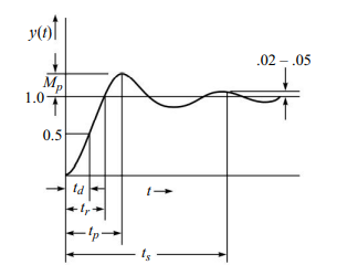
1. Delay time, td
Delay time is the time that it takes the system to reach one-half of the final value for the first time.
2. Rise time, tr
Rise time is the time that it takes the system to go from 10 to 90 percent, 5 to 95 percent or 0 to 100 percent of the final value.
3. Peak time, tp
Peak time is the time that it takes the system to reach the maximum overshoot for the first time
4. Maximum overshoot, Mp
Maximum overshoot is the maximum peak value measured from the steady state value in Fig. 3.10.
5. Settling time, ts
Settling time is the time required for the system to stay within a range about the final value. This is usually within 2 and 5 percent
Figure 3.10 illustrates these system parameters. In some cases, certain of the parameters are not relevant. In the case of a critically damped system there is no overshoot and hence Mp and tp do not apply. In robotics, it is sometimes critical that the system not be allowed to overshoot, while in other applications it may be necessary for the sake of speed, to allow overshoot. The balancing of these parameters when designing the system is the responsibility of the controls engineer.
Steady-State Response
The steady-state analysis of a control system is concerned with determining the response of the system after the transient response has disappeared. It is assumed that the system of interest is one which is stable. In steady-state analysis, the system designer wants to know whether the system will achieve the desired final value as designer wants to know whether the system will achieve the desired final value as time of operation increases.
One approach to the problem would be to solve the differential equation of the system as it is subjected to some appropriate input.
Depending on the degree of difficulty of the differential equation, this could prove to be a difficult approach. A more direct method is to make use of the final value theorem from control theory which uses the Laplace transform of the system output.
The final value theorem states that the final value of the function is given by

where F(s) is the Laplace transform of the function f(t). Implicit in the above statement of the final vaue theorem is that the limit of f(t) exists as time approaches infinity
Robot Sensor
Sensors is a device which detects an input signal and responds to it
A robot moves in space to perform tasks and hence it needs actuators to move the links and sensors to know where each joint is. Sensors inform the controller by how much each joint has moved and thus enables the controller to enforce a particular velocity or position during motion.
Sensors can be divided into two parts:
1. Internal sensors: These are responsible for the internal working of the robot and are mainly used for closing the loop in feedback control e.g., position sensors. A robot cannot function properly without these if it is using a closed loop feedback control system. The main internal sensors are position and velocity sensors.
2. External sensors: These are responsible for interaction with the environment. A robot can use external sensors like touch sensor for interaction with the environment. In case any of these sensors fail the robot can still function but its ability to interact with the external world is reduced. External sensors are of many different types depending on the kind of interaction with the environment. The main external sensors are force/torque sensors, vision, touch, pressure sensors, etc.
Position& Velocity Sensors
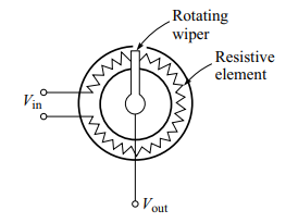
Potentiometers: Potentiometers are analog devices whose output voltage is proportional to the position of a wiper. Fig. 3.11 illustrates a typical pot.
A voltage is applied across the resistive element. The voltage between the wiper and ground is proportional to the ratio of the resistance on one side of the wiper to the total resistance of the resistive element.
Essentially the pot acts as a voltage divider network. That is, the voltage across the resistive element is divided into two parts by a wiper. Measuring this voltage gives the position of the wiper. The function of the potentiometer can be represented by the following function:

where Vo(t) is the output voltage, Kp is the voltage constant of the pot in volts per radian (or volts per inch in the case of a linear pot) and θ(t) is the position of the pot in radians (or inches). Since a pot requires an excitation voltage, in order to calculate Vo, we can use

where Vex is the excitation voltage, qtot is the total travel available of the wiper, and qact is the actual position of the wiper.
Potentiometers can be single turn in which the rotating wiper can move only by 360° or they can also be multi turn in which the rotating wiper can move by several 360° turns. Potentiometers suffer from disadvantages like non-linearity and low life due to the continuous friction between the wiper and the variations in the resistive element. In addition, the variation in wiper contact between the coil and the wiper can lead to noise in position measurement.
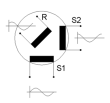
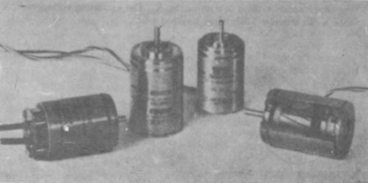
Resolvers: A resolver is another type of analog device whose output is proportional to the angle of a rotating element with respect to a fixed element. In its simplest form, a resolver has a single winding on its rotor and a pair of windings on its stator. The stator windings are 90° apart as shown in Fig. 3.12. If the rotor is excited with a signal of the type A sin(wt) the voltage across the two pairs of stator terminals will be

where θ is the angle of the rotor with respect to the stator. This signal may be used directly, or it may be converted into a digital representation using a device known as a ‘resolver-to-digital’ converter. Since a resolver is essentially a rotating transformer, it is important to remember that an ac signal must be used for excitation. If a dc signal were used there would be no output signal
Encoders:
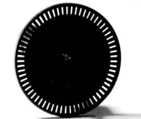
As microprocessors have become cheaper and with a move towards digital electronics, the encoder is virtually used everywhere for position measurement. Almost all industrial robots, NC machines, etc., use encoders to measure the position and velocity of motion. Encoders are available as two basic types: incremental and absolute. A simple incremental encoder is illustrated in Fig. 3.13
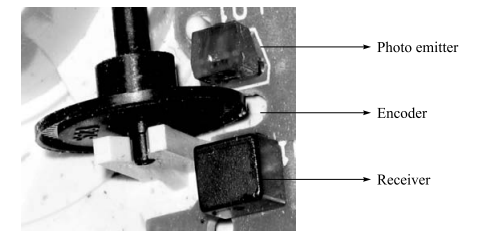
An incremental encoder consists of a disk marked with alternating transparent and opaque stripes aligned radially. A photo transmitter (a light source) is located on one side of the disk and a photo receiver is on the other Fig. 3.14.
As the disk rotates, the light beam is alternately completed and broken. The output from the photo receiver is a pulse train whose frequency is proportional to the speed of rotation of the disk. In a typical encoder, there are two sets of photo transmitters and receivers aligned 90° out of phase.
This phasing provides direction information, that is, if signal A leads to signal B by 90° the encoder disk is rotating in one direction, if B leads A then it is going in the other direction. By counting the pulses and by adding or subtracting based on the sign, it is possible to use the encoder to provide position information with respect to a known starting location.
Normally, two incremental encoders are used in parallel so that the resolution of measurement is increased. These two signals are passed through an XOR gate. It can be seen that the resolution of the resulting signal is now increased two times, as we now have two pulses in place of only one pulse from each encoder.
Most modern position control systems have two or more encoders in parallel to increase the resolution of the systems. The rate at which the pulses are generated by the encoder can also be counted to get an estimate of the velocity of the rotating shaft. Hence, an encoder can also be used as a velocity sensor.
Absolute Encoders:
In some cases, it is desirable to know the, position of an object in absolute terms, that is, not with respect to a starting position.
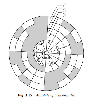
For this an absolute encoder could be used. Absolute encoders employ the same basic construction as incremental encoders except that there are more tracks of stripes and a corresponding number of receivers and transmitters.
Usually the stripes are arranged to provide a binary number proportional to the shaft angle. The first track might have two stripes, the second four, and the third eight and so on. In this way the angle can be read directly from the encoder without any counting being necessary. Figure 3.15 illustrates an absolute encoder.
The resolution of an absolute encoder is dependent on the number of tracks and is given by Fig. 3.15 Absolute optical encoder.
resolution = 2n
where n is the number of tracks on the disk.
VELOCITY SENSORS
Velocity information is required for closed loop feedback control using a PD or PID controller. One of the most commonly used devices for the feedback of velocity information is the dc tachometer.
A tachometer is essentially a dc generator providing an output voltage proportionate to the angular velocity of the armature. Velocity information can also be obtained from an incremental encoder in which the rate at which the dark and transparent slots cross the emitter receiver pair indicate the velocity of the rotating shaft. Figure 3.16 illustrates a typical dc tachometer. A tachometer can be described by the relation,


where Vo(t)is the output voltage of the tachometer in volts, Kt(t) is the tachometer constant, usually in V/rad/s and is the angular velocity in radians per second.
Tachometers are generally used to provide velocity information to the controller. This can be used for performing velocity control of a device or, in many cases, to increase the value of Kd in a system, thereby improving the stability of the system and its response to disturbances.
Direct current tachometers provide a voltage output proportional to the armature rotational velocity, hence they are analog devices. There is a digital equivalent of the dc tachometer which provides a pulse train output of a frequency proportional to the angular velocity.
ACTUATORS
Actuators are the devices which provide the actual motive force for the robot joints. They commonly get their power from one of three sources: compressed air, pressurized fluid or electricity. They are called pneumatic, hydraulic or electric actuators respectively.
Pneumatic and Hydraulic Actuators
Pneumatic and hydraulic actuator are both by moving fluids. In the first case the fluid is compressed air and in the second case, the fluid is usually pressurized oil
The operation of these actuator is generally similar expect in their ability to contain the pressure of the fluid. Pneumatic systems typically operate at about 100lb/in2 and hydraulic systems at 1000 to 3000 lb/in2
The simplest fluid power device is the cylinder as shown in fig. which could be used to actuate a linear joint by means of a moving piston.
This example is called a single-ended cylinder as the piston rod only comes out of the cylinder at one end. Other types of cylinders include double-ended cylinders and rodless cylinders.
There are two relationships of particular interest when discussing actuators: the velocity of the actuator with respect to the input power and the force of the actuator with respect to the input power. For the cylinder type actuator these relationships are given by
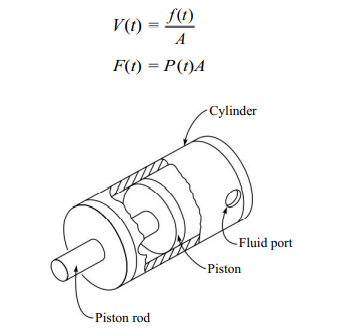
Where V(t) is the velocity of the piston f(t) is the fluid flow rate (volumetric) F(t) is the force, P(t) is the pressure of the fluid and A is the area of the piston. n. Since the requirements of a robot are to carry a payload at a given speed, we can use the relations described for choosing the appropriate actuator.
Electric Motors
As their capabilities improve, electric motors are becoming more and more the actuator of choice in the design of robots. They provide excellent controllability with a minimum of maintenance required. There are a variety of types of motors in use in robots; the most common are dc servomotors, stepper motors, and ac servomotors.
DC motors that are used in closed loop position control are called servo motors. As servo motors are required to have very large acceleration or deceleration in order to have faster response, the armatures of these motors are specially designed to have low inertia. DC servo motors can be either brushed motors or brushless motors.
The basic construction difference between a brushed and brushless motor is that in a brushless motor, the armature winding are in the stator and the permanent magnets are in the rotor. While in a brushed motor, the armature windings are in the rotor and the permanent magnets are in the stator.
Figure 3.18 shows a typical dc servomotors with a permanent magnet stator and winding on rotor. The main components of the dc servomotor are the rotor and the stator. Usually, the rotor includes the armature and the commutator assembly and the stator includes the permanent magnet and brush assemblies.
When current flows through the winding of the armature it sets up a magnetic field opposing the field set up by the magnets. This produces a torque on the rotor. As the rotor rotates, the brush and commutator assemblies switch the current to the armature so that the field remains opposed to the one set up by the magnets
In this way, the torque produced by the rotor is constant throughout the rotation. Since the field strength of the rotor is a function of the current through it, it can be shown that for a dc servomotor


where Tmis the torque of the motor, Ia is the current flowing through the armature, and Km is the motor’s torque constant.
Stepper Motors
Stepper motors (also called stepping motors) are a unique type of actuator and have been used mostly in computer peripherals. A stepper motor provides output in the form of discrete angular motion increments.
It is actuated by a series of discrete electrical pulses. For every electrical impulse there is a single-step rotation of the motor shaft. In robotics, stepper motors are used for relatively light duty applications.
Also, stepper motors are typically used in open-loop systems rather than the closed-loop systems. Figure 3.21 provides a schematic representation of one type of stepper motor.
The stator is made up of four electromagnetic poles and the rotor is a two-pole permanent magnet. If the electromagnetic stator poles are activated in such a way that pole 3 is N (magnetic North) and pole I is S then the rotor is aligned as illustrated. If the stator is excited so that pole 4 is N and pole 2 is S, the rotor makes a 90° turn in the clockwise direction.
By rapidly switching the current to the stator electronically, it is possible to make the motion of the rotor appear continuous.

The resolution (number of steps per revolution) of a stepper is determined by the number of poles in the stator and rotor. The relation between a stepper motor’s resolution and its step angle is given by
n = A/360°
where n is the resolution and A is the step angle.
This maximum torque is known as the holding torque of the motor. It is possible to increase the resolution of a stepper by using a technique known as half-stepping or micro-stepping.
By applying current to more than one set of field windings, it is possible to make the rotor seek out an ‘average’ position. Of course, when using this technique the holding torque is reduced.
AC Servomotors and Other Types
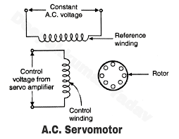
Recent advances in control electronics are producing ac servomotors. These motors have the advantages of being cheaper to manufacture than dc motors; they have no brushes, and they possess a high power output.
With proper electronics package, however, their performance can be made to look very much like the performance of a dc motor. Another type of electric motor is the brushless dc motor. It is constructed like an ‘inside-out’ dc motor. It has a permanent magnet rotor and an electromagnetic stator. Instead of using brushes, however, commutation is performed electronically using an encoder to inform the electronics of the relative positions of the stator and rotor.
Also available are linear electric motors. Their construction is similar to a dc servomotor that has been cut open and flattened out.
In almost all cases of electric motors the limit factor on power output is heat dissipation. Some of the current used in the motor must be dissipated as heat.
Two ways to increase the performance of a motor is to remove heat more quickly or to reduce the current requirements. The latter may be done by increasing the magnetic flux of the permanent magnets.
Recent advance is magnetic materials are allowing for performance improvements of almost 10 times with the same power requirements
