
Industrial Robotics 4th Module
Transducers and Sensors
A transducer is a device that converts one type of physical variable (e.g., force, pressure, temperature etc.) into another form.
A common conversion is to electrical voltage, and the reason for making the conversion is that the converted signal is more convenient to use and evaluate a digital computer.
A sensor is a device which detects am input signal and responds to it. Some of the common sensors include thermocouples (temperatures), speedometers (velocity) and Pilot tubes (flow rate).
Any sensor or transducer requires calibration in order to be useful as a measuring device. Calibration is the procedure by which the relationship between the measured variable and the converted output signal is established.
Transducers and sensors can also be classified into two basic types depending on the form of converted signal. The two types are
1. Analog transducers
2. Digital transducers
Analog transducers provide a continuous analog signal such as electrical voltage or current. This signal can then be interpreted as the value of the physical variable that is being measured.
Digital transducers produce a digital output signal, either in the form of a set of parallel status bits or a series of pulses that can be counted.
In either form, the digital signal represents the value of the measured variable. Digital transducers are becoming more popular because of the ease with which they can be read as separate measuring instruments. In addition, they offer the advantage in automation and process control that they are generally more compatible with the digital computer than analog-based sensors.
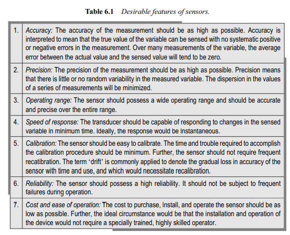
In order to be useful as measuring devices, in robotics and in other applications, sensors must possess certain features. Some of the desirable engineering features of these desirable features of sensors and transducers are present in table below
Sensors in Robotics
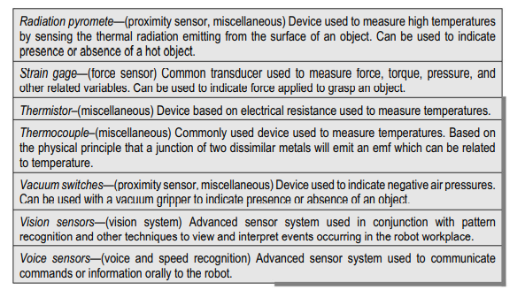
Sensors used in robotics mainly for interaction with the environment include a wide range of device which can be divided into the following general catehories:
· Tactile sensors
· Proximity and range sensors
· Miscellaneous sensors and sensor-based systems
· Machine vision systems
Tactile sensors
Tactile sensors are devices which indicate contact between themselves and some other solid object. Tactile sensing devices can be divided into two classes: touch sensors and force sensors.
· Touch Sensors
Touch sensors are used to indicate the contact has been made between two objects without regard to the magnitude of the contacting force. Included within this category are simple devices such as limit switches, microswitches and the like.
The simpler devices are frequently used in the design of interlock systems in robots. For example they can be used to indicate the presence or abscene of parts in a fixture or at the pick up point along a conveyer.
Another use for a touch sensing device would be as a part of an inspection probe which is manipulated by the robot to measure dimensions on a work part.
· Force Sensors
Force sensors indicate not only that contact has been made with the object but also the magnitude of the contact force between the two objects.
The capacity to measure forces permits the robot to perform a number of tasks. These include the capability to grasp parts of different sizes in material handling, machine loading and assembly work, applying the appropriate level of force for the given part.
In assembly applications, force sensing could be used to determine if the screws have become cross-threaded or if the parts are jammed
Force sensing in robotics can be accomplished in several ways.
Force sensing wrist
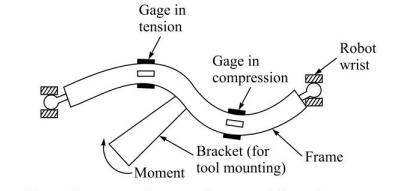
The purpose of force sensing wrist is to provide information about the three components of force (Fx, Fy, and Fz) and the three moments (Mx, My and Mz) being applied at the end effector. Fig shows the construction of force sensing wrist
The device consists of a metal bracket fastens to a rigid frame. The frame is mounted to the wrist of the robot and the tool is mounted to the centre of the bracket. The fig shows how the sensors might react to a moment applied to the bracket due to force and moments on the tool
The controller would perform the following sequence of operations:
· Measure the forces at the wrist in each axis direction
· Calculate the force offsets required. The force offset in each direction is determined by subtracting the desired force from the measured force.
· Calculate the torques to be applied by each axis to generate the desired force offset at the wrist. These are moment calculations which take into account the combined effects of the various joints and links of the robot.
· Then the robot must provide the torques calculated in step 3 so that the desired forces are applied in each direction.
Joint Sensing
If the robot uses dc servometers then the torque being exerted by the motors is propotional to the current flowing through the armature. A simple way to measure this current is to measure the voltage drop across a small precision resistor in series with the motor and power ampilifer.
This simplicity makes this technique attractive; however measuring the joint torque has several disadvantages. First, measurements are made in joints space, while the force of interest are applied by the tool and would be more useful if made in tool space
One area where joint torque sensing shows promise of working well is with direct drive robots. Direct drive robots are a relatively new innovation in which the drive motors are located at the joints of the manipulator.
Tactile array sensors
A tactile array sensor is a special type of force sensor composed of a matrix of force-sensing elements. The force data provided by this type of device may be combined with pattern recognition techniques to describes a number of characteristics about the impression contacting the array sensors surface.
Among these characteristics are
· The presence of an object
· The object’s contact area, shape, location, and orientation.
· The pressure and pressure distribution
· Force magnitude and location
Tactile array sensors can be mounted in the fingers of the robot gripper or attached to a work table as a flat touch surface
Proximity and range sensors
Proximity sensors are devices that indicate when one object is dose to another object. How close the object must be in order to activate the sensor is dependent on the particular device. The distance can be anywhere between several millimetres and several feet.
Some of these sensors can also be used to measure the distance between the object and the sensor, and these devices are called range sensors.
Proximity and range sensors would typically be located on the wrist or end effector since these are moving parts of the robot.
One practical use of proximity sensor in robotics would be to detect the presence or absence of a workpart or other object. Another important application is for sensing human beings the robot workcell
A variety of technologies are available for designing proximity and range sensors. These technologies include optical devices, acoustics, and electrical field techniques.
Optical proximity sensors can be designed using either visible or invisible light sources. Infrared sensors may be active or passive. The active sensors send out an infrared beam and respond to the reflection of the beam against a target.
This infrared-reflectance sensor using an incandescent light source is a common decive that is commercially available. The active infrared sensors can be used to indicate whether or not a part is present
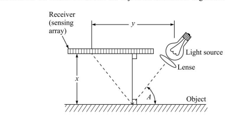
Another optical approach for proximity sensing involves the use of a collimated light beam and a linear array of light sensors. By reflecting the light beam off the surface of the object, the location of the object can be determined from the position of its reflected beam on the sensor array
Uses of sensors in robotics.
Major use of sensors in robotics can be divided into four categories:
· Safety Monitoring
One of the important applications of sensor technology in automated manufacturing operation is safety or hazard monitoring which concerns the protection of human workers who work in the vincity of the robot or other equipment.
· Interlocking in work cell control
The second major use of sensor technology in robotics is to implement interlocks in work cell control. Interlocks are used to coordinate the sequence of activities of different pieces of equipment in the work cell.
In the execution of the robot program, there are certain elements of the work cycle whose completion must be verified before proceeding with the next element in the cycle. Sensors often very simple devices are utilized to provide with the next element in the cycle.
· Part inspection for quality control
The third category is quality control. Sensors can be used to determine a variety of part quality characteristics. Traditionally, quality control has been performed using manual inspection techniques on a statistical sampling basis. The use of sensors permits the inspection operation to be performed automatically on a 100 percent basis in which every part is inspected
The limitation on the use of automatic inspection is that the sensor system can only inspect for a limited range of part characteristics and defects. For example, a sensor probe designed to measure part length cannot detect flaws in the part surface.
· Determining positions and related information about objects in the robot cell
The fourth major use of sensors in robotics is to determine the positions and other information about various objects in the work cell (e.g., work parts, fixtures, people, equipment etc.). In addition to positional data about a particular object, other information required to properly execute the work cycle might include the object’s orientation, color, size and other characters ics
Reasons why this kind of data would need to be determined during program execution include
- Work part identification and
-Random position and orientation of parts in the work cell
Accuracy requirements in a given application exceed the inherent capabilities of the robot. Feedback information is required to improve the accuracy of the robot’s positioning
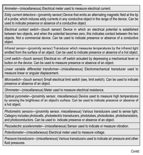
Sensor devices used in robot workcells
Machine Vision: Introduction to machine vision
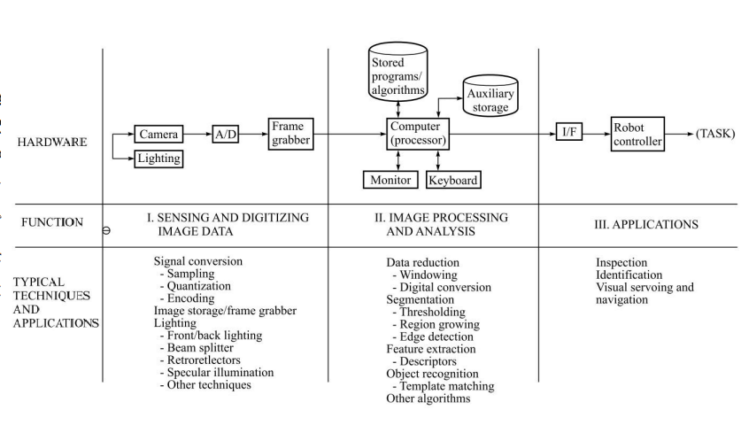
Machine vision is concerned with the sensing of vision data and its interpretation by a computer. The typical visison system consists of the camera and digitizing hardware,a digital computer and hardware and software necessary to interface them. This interface hardware and software is often referred to as a pre-processor. The operation of the vision system consists of three functions:
1. Sensing and digitizing image data
The sensing and digitizing functions involve the input of vision data by means of a camera focused on the scene of interest. Special lighting techniques are frequently used to obtain an image of sufficient contrast for later processing. The image viewed by the camera is typically digitized and stored in computer memory.
The digital image is called frame of vision data and is frequently captured by a hardware device called as frame grabber. These devices are capable of digitizing images at the rate of 30 frames per second.
2. Image processing and analysis
The digitized image matrix for each frame is stored and then subjected to image processing and analysis functions for data reduction and interpretation of the image. These steps are required in order to permit the real-time application of vision analysis required in robot applications.
Typically an image frame will be threshold to produce a binary image and then various feature measurements will further reduce the data representation of the image. This data reduction can change the representation of a frame from several hundred thousand bytes of raw image data to several hundred bytes of feature value data. The resultant feature data can be analysed in the available time for action by the robot system.
3. Application
The third function of a machine vision system is the applications function. The current applications of machine vision in robotics include inspection part identification, location and orientation.
The relationship between three function is shown in fig
Sensing and digitizing function in machine vision
Image sensing requires some type of image formation device such as a camera and a digitizer which stores a video frame in the computer memory. We divide the sensing and digitizing functions into several steps.
The initial step involves capturing the image of the scene with the vision camera. The image consists of relative light intensities corresponding to the various portions of the scene. These light intensities are continuous analog values which must be sampled and converted into a digital form.
The second step, digitizing, is achieved by an analog to digital converter. The A/D converter is either part of a digital video camera or the front end of a frame grabber. The choice is dependent on the type of hardware in the system.
The frame grabber representing the third step, is an image storage and computational device which stores a given pixel array. The frame grabber can vary in capability from one which simply stores an image to significant computation capability.
In the more powerful frame grabbers, thresholding, windowing and histogram modification calculations can be carried out under computer control. The stored image is then subsequently processed and analysed by the combination of the frame grabber and the vision controller.
Robotic applications
Robotic application of machine vision fall into three broad categories listed below:
· Inspection
The first category is one in which the primary function is the inspection process. This is carried out by the machine vision system, and the robot us used in a secondary to support the application.
The objectives of machine vision inspection include checking for gross surface defects, discovery of flaws in labelling, verification of the presence of components in assembly and checking for the presence of holes and other features in a part.
When these kinds of inspection operations are performed manually, there is a tendency for human error. Also the time required in most manual inspection operations require that the procedures are carried out automatically using 100 percent inspection and usually in much less time.
· Identification
This is concerned with applications in which the purpose of the machine vision system is to recognise and classify an object rather than to inspect it. Inspection implies that the part must be either accepted or rejected. Identification involves a recognition process in which the “part itself, or its position and/or orientation, is determined.
This is usually followed by subsequent decision and action taken by the robot. Identification applications of machine vision include part sorting, palletizing and depalletizing and picking parts that are randomly oriented from a conveyer or bin.
· Visual servoing and navigation
In the third category, visual servoing and navigation control, the purpose of the vision system is to direct the actions of the robot based on its visual input.
The generic example of robot visual servoing is where the machine vision system is used to control the trajectory of the robot’s end effector toward an object in the workspace. Industrial examples of this application include part positioning, retrieving parts moving along a conveyor, retrieving and reorienting parts moving along a conveyor, assembly etc.

