
Industrial Robotics 5th Module
Robot Programming: METHODS OF ROBOT PROGRAMMING
Robot programming is accomplished in several ways. Consistent with current industrial practice we divide the programming methods into two basic types:
1. Leadthrough methods
2. Textual robot languages
The leadthrough methods require the programmer to move the manipulator through the desired motion path and that the path be committed to memory by the robot controller. The leadthrough methods are sometimes referred to as ‘teach-by-robot programming methods used in industry.
Robot programming with textual languages is accomplished somewhat like computer programming. The programmer types in the program on a CRT (cathode ray tube) monitor using a high-level English-like language.
LEADTHROUGH PROGRAMMING METHODS
In lead through programming, the robot is moved through the desired motion path in order to record the path into the controller memory.
There are two ways of accomplishing lead through programming:
1. Powered lead through
The powered lead through method makes use of a teach pendant to control the various joint motors, and to power drive the robot arm and wrist through a series of points in space. Each point is recorded into memory for subsequent play back during the work cycle. The teach pendant is usually a small handheld control box with combinations of toggle switches, dials, and buttons to regulate the robot’s physical movements and programming capabilities.
Among the various robot programming methods, the powered lead through method is probably the most common today. It is largely limited to point-to-point motions rather than continuous movement because of the difficulty in using the teach pendant to regulate complex geometric motions in space.
A large number of industrial robot applications consist of point-to-point movements of the manipulator. These include part transfer tasks, machine loading and unloading, and spot welding.
2. Manual lead through
The manual leadthrough method (also sometimes called the ‘walkthrough’ method) is more readily used for continuous-path programming where the motion cycle involves smooth complex curvilinear movements of the robot arm.
The most common example of this kind of robot application is spray painting, in which the robot’s wrist, with the spray painting gun attached as the end effector, must execute a smooth, regular motion pattern in order to apply the paint evenly over the entire surface to be coated.
Continuous arc welding is another example in which continuous-path programming is required and this is sometimes accomplished with the manual leadthrough method.
In the manual leadthrough method, the programmer physically grasps the robot arm (and end effector) and manually moves it through the desired motion cycle. If the robot is large and awkward to physically move, a special programming apparatus is often substituted for the actual robot. This apparatus has basically the same geometry as the robot, but it is easier to manipulate during programming.
A robot program as a path in space
The locus of points along the path defines the sequence of positions through which the robot will move its wrist.
In most applications, an end effector is attached to the wrist, and the program can be considered to be the path in space through which the end effector is to be moved by the robot.
Since the robot consists of several joints (axes) linked together, the definition of the path in space in effect requires that the robot move its axes through various positions in order to follow that path.
For a robot with six axes, each point in the path consists of six coordinate values. Each coordinate value corresponds to the position of one joint.
There are four basic robot anatomies: polar, cylindrical, cartesian, and jointed arm. Each one has three axes associated with the arm and body configuration and two or three additional joints associated with the wrist.
The arm and body joints determine the general position in space of the end effector and the wrist determines its orientation.
If we think of a point in space in the robot program as a position and orientation of the end effector, there is usually more than one possible set of joint coordinate values that can be used for the robot to reach that point.
For example, there are two alternative axis configurations that can be used by the jointed-arm robot shown in fig to achieve the target point indicated.
We see in the figure that although the target point has been reached by both of the alternative axis configurations, there is a difference in the orientation of the wrist with respect to the point.
We must conclude from this that the specification of a point in space does not uniquely define the joint coordinates of the robot.
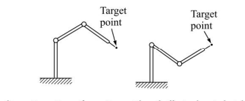
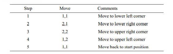
Figure 8.2 shows the four possible points in the robot’s rectangular workspace
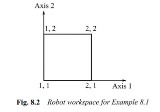
. A program for this robot to start in the lower left-hand corner and traverse the perimeter of the rectangle could be written as follows:
Motion interpolation
The following interpolation schemes are available in most of the robot controllers.
· Joint interpolation
· Straight line interpolation
· Circular interpolation
· Irregular smooth motions (manual lead through programming).
Joint interpolation: The controller determines how far each joint must move to get from the first point defined in the programme to the next. It then selects the joint that requires the longest time. This determines the amount of movement for other axes such that all the axes start and stop at the same time. Joint interpolation is the default procedure for many commercial robots.
Straight-line interpolation: In this interpolation, the robot controller computes the straight-line path between two points and develops the sequence of addressable point along the path for the robot to pass through.
Circular interpolation: This requires the programmer to define a circle in the robot’s workspace. This is done by specifying three points that lie along the circle. The controller constructs the circle by selecting a series of points that lie closer to the circle. These movements are actually small straight lines. If the addressable points are dense then the linear approximation becomes very much like circle.
Circular interpolation is more readily programmed using a textual programming language than with leadthrough techniques
Manual lead through Programming: When the manipulator wrist is moved by the programmer to teach spray painting or arc welding, the movements consist of combination of smooth motion segments. These segments are sometimes approximately straight lines or curves or back and forth motions. These movements are referred as irregular smooth motions and an interpolation is involved to achieve them.
Wait, signal and delay commands
Nearly all industrial robots can be instructed to send signals or wait for signals during execution of the program. These signals are sometimes called interlocks. The most common form of interlock signal is to actuate the robot’s end effector. In the case of a gripper, the signal is to open or close the gripper.
Signals of this type are usually binary; that is, the signal is on-off or high-level-low-level. Binary signals are not readily capable of including any complex information such as force sensor measurements. The binary signals used for the robot gripper are typically implemented by using one or more dedicated lines.
Air pressure is commonly used to actuate the gripper. A binary valve to actuate the gripper is controlled by means of two interlock signals, one to open the gripper and the other to close it. In some cases, feedback signals can be used to verify that the actuation of the gripper had occurred, and interlocks could be designed to provide this feedback data.
In addition to control of the gripper, robots are typically coordinated with other devices in the cell also. For example, let us consider a robot whose task is to unload a press. It is important to inhibit the robot from having its gripper enter the press before the press is open, and even more obvious, it is important that the robot remove its hand from the press before the press closes. To accomplish this coordination, we introduce two commands that can be used during the program. The first command is
SIGNAL M
which instructs the robot controller to output a signal through line M (where M is one of several output lines available to the controller). The second command is
WAIT N
which indicates that the robot should wait at its current location until it receives a signal on line N (where N is one of several input lines available to the robot controller).
With use of delay, the robot would be programmed to wait for the command for this second case has a length of time as its argument rather than an input line. The command
DELAY X SEC
indicates that the robot should wait X seconds before proceeding to the next step in the program
Example Program
Let us suppose that the two-axis robot is to be used to perform the unloading of the press in our example. The layout of the workcell is illustrated in Fig. 8.9,
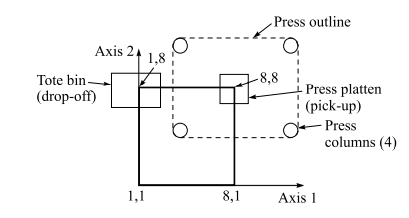
The platten of the press (where the parts are to be picked up) is located at 8,8. The robot must drop the parts in a tote pan located at 1,8. One of the columns of the press is in the way of an easy straight line move from 8,8 to 1,8. Therefore, the robot must move its arm around the near side of the column in order to avoid colliding with it. This is accomplished by making use of points 8,1 and 1,1. Point 8,1 will be our position to wait for the press to open before entering the press to remove the part, and the robot will be started from point 1,1, a point in space known to be safe in the application.
The following is our program to accomplish the press unloading task (the sequence begins with the gripper in the open position)
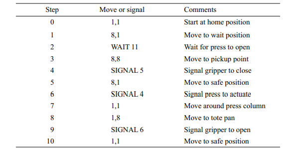
Each step in the program is executed in sequence, which means that the SIGNAL and WAIT commands are not executed until the robot has moved to the point indicated in the previous step.
The operation of the gripper was assumed to take place instantaneously so that its actuation would be completed before the next step in the program was started. Some grippers use a feedback loop to ensure that the actuation has occurred before the program is permitted to execute the next step.
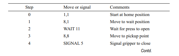
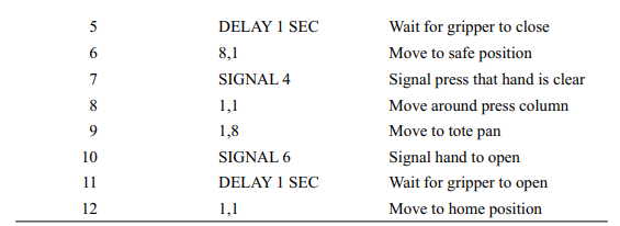
An alternative way to address this problem is to cause the robot to delay before proceeding to the next step.
Below is a modified version of above example using time as the means for assuring that the gripper is either opened or closed
Branching
Most controllers for industrial robots provide a method of dividing a program into one or more branches. Branching allows the robot program to be subdivided into convenient segments that can be executed during the program.
A branch can be thought of as a subroutine that is called one or more times during the program. The subroutine can be executed either by branching to it at a particular place in the program or by testing an input signal line to branch to it. The amount of decision logic that can be incorporated into the program varies widely with controllers
A frequent use of the branch capability is when the robot has been programmed to perform more than one task. In this case, separate branches are used for each individual task. Some means must be devised for indicating which branch of the program must be executed and when it must be executed.
A common way of accomplishing this is to make use of external signal which are activated by sensors or other interlocks. The device recognizes which task must be performed, and provides the appropriate signal to call that branch. This method is frequently used on spray painting robots which have been programmed to paint a limited variety of parts moving past the workstation of a conveyor.
Capabilities and limitations of lead-through methods
Some of the teach pendants used for commercially available robots possess a wide range of capabilities.
Defining points in space or setting the speed can be easily done using the toggle switches and dials of a simple teach pendant.
For WAIT, SIGNAL, and DELAY commands, special buttons must be added to the pendant or these functions must be defined using the console at the main controller.
Programming of branches can also be accomplished with a teach pendant in various ways.
For example, a branch can be executed by using a toggle switch mounted either on the teach pendant or on the controller itself. When this method is used, there are several toggle switches corresponding to a predetermined set of branches.
Although the leadthrough programming controls offer the above capabilities, there are certain inherent limitations with the leadthrough methods. These limitations can be summarized as follows:
1. The robot cannot be used in production while it is being programmed.
The fact that leadthrough programming requires the presence of the robot precludes the use of the robot in production. This has important economic implications. Since programming takes time away from production, it means that the batch size of parts to be produced by the robot must be sufficiently large to minimize the contribution of the programming cost. If the lot size is too small, it might take longer to prepare the program than to run it.
2. As the complexing of the program increases, it becomes more difficult to accompolish lead through programming using the currently available methods.
The second limitation deals with the fact that robots are being employed in production applications of increasing complexity, and being called on to perform increasingly sophisticated functions. With the lead through methods, it is difficult to program these kinds of functions.
With the various robot programming functions, it has become more and more difficult to describe the individual steps that are to be performed by the robot without resorting to some form of computer like coding. It is more difficult to define many of the non-motion activities with a teach pendant than with a textual programming language.
3. Lead through programming is not readily compatible with modern computer based technologies such as CAD/CAM, data communications networking, and integrated manufacturing information systems
The third limitation is concerned with the problem of interfacing robots to other computer-based systems in the corporation. One of the important goals in manufacturing is to establish computer-integrated manufacturing (CIM) systems in which the data and information necessary to make a product is captured originally on a CAD/CAM data base, and downloaded through the various manufacturing planning steps ultimately to the shop floor where robots and other automated systems work.
The various components of the CIM system need to be able to communicate with each other and with the central plant computer. The use of lead through programming procedures does not lend itself to the communications and data base requirements of this kind of computer-integrated factory. Textual robot languages are more suited to these needs.

