
Material Science 2nd Module
TTT Curve or TTT Diagram
Time temperature transformation diagram are plots of temperature versus time (usually on a logarithmic scale)
They are generated from percentage transformation-vs time measurements and are useful for understanding the transformations of an alloy steel at elevated temperatures.
Time temperature transformation diagram is also known as isothermal transformation diagrams
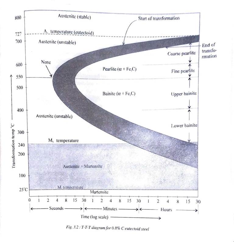
TTT – DIAGRAM FOR 0.8% C EUTECTOID STEEL
TTT diagram are drawn with temperature along Y -axis and time along X – axis to study the effects of time on transformation of phases. Fig 3.2 illustrates the TTT Diagram for 0.8%C eutectoid steel. From the Fe-Fe3C phase diagram we know that steel containing 0.8%C is completely austenitic above 727° C.
This austenite transforms into pearlite upon slow cooling but for much higher rates of cooling other phases like bainite, (upper or lower), martensite or even austenite itself can result in the microstructure. All these appear on TTT Diagram.
TTT diagram basically consists two parallel curves which represent the beginning and ending of transformation of austenite, respectively. Another set of parallel horizontal lines represent the martensite start and finish temperatures respectively
Drawing of TTT Diagram
The steps followed to determine a TTT diagram are:
Step 1 :
A large number of identical samples are cut and prepared from the same bar. The cross section of samples has to be small in order to react quickly to the changes in temperature.
Step 2:
All the samples are placed in a furnace at the proper austenitizing temperature for sufficient duration until complete austenite phase in the microstructure is ensured
Step 3:
A set of samples are then transferred to molten salt bath held at a constant subcritical temperature (below 727°C and for example 700°C)
Step 4:
Each sample in the set held in the molten salt bath at this constant temperature for different intervals of time and then quenched
Step 5:
After cooling each sample is checked for hardness and studied microscopically.
Step 6:
The above steps are repeated for samples held at different sub-critical temperatures until sufficient points are determined to plot the curves on the diagram
The above procedure is carried out to draw the TTT diagram for one composition of iron and carbon. The entire effort is carriedout to draw the TTT diagramfor each composition of iron and carbon.
Factors affecting TTT Diagram
1. Grain Size
2. Carbon Content
3. Alloying elements
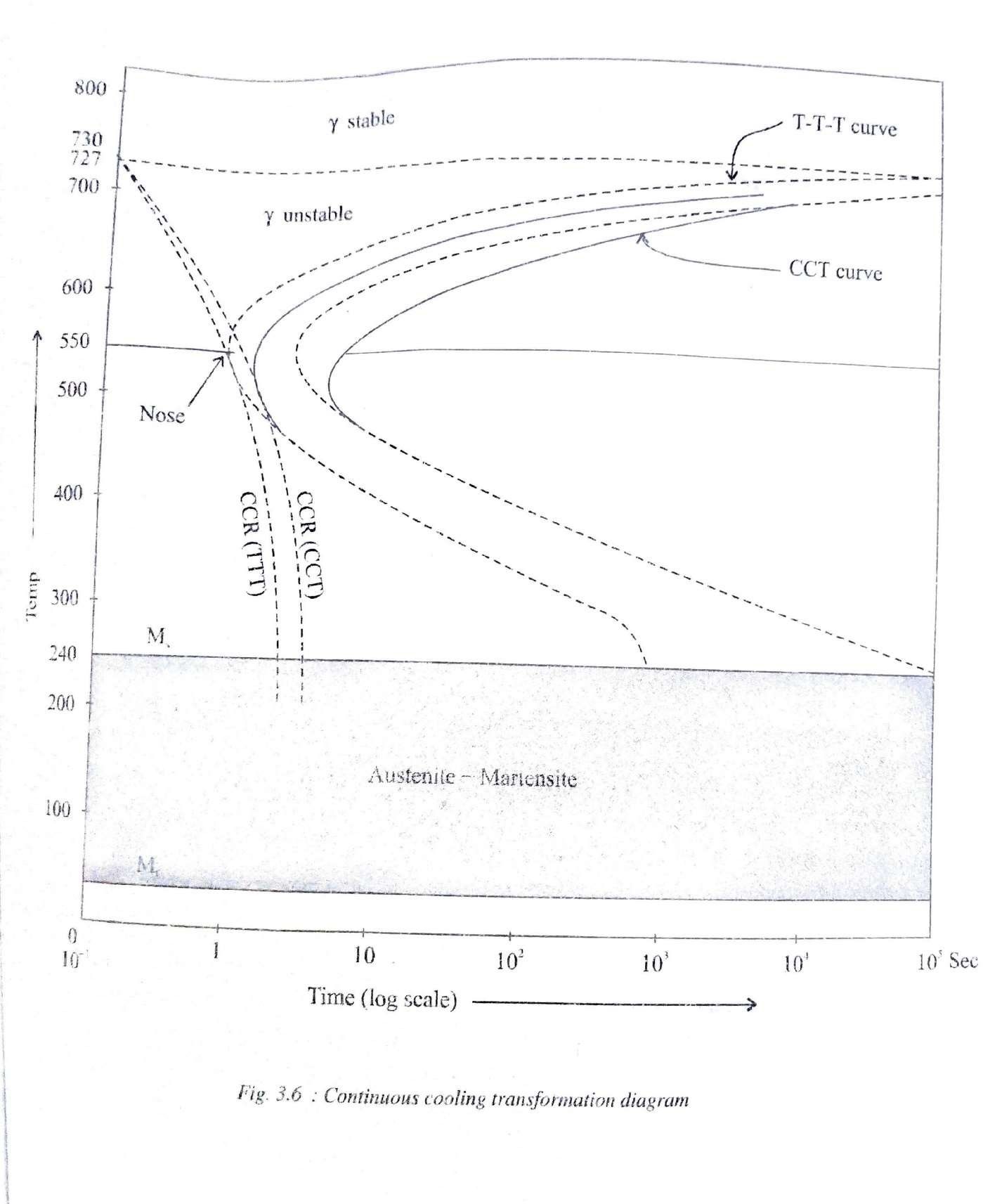
Continous Cooling Curves (CCT Diagram)
A continuous cooling transformation (CCT)phase diagram is often used when heat treating steel. These diagrams are used to represent which types of phase changes will occur in a material as it is cooled at different rates.
These diagrams are often more useful than time-temperature-transformation diagrams because it is more convenient to cool materials at a certain rate (temperature-variable cooling),than to cool quickly and hold at a certain temperature (isothermal cooling).
TTT curve vs CCT curve (Difference between TTT and CCT)
TTT diagrams are constructed by taking Isothermal transformation whereas CCT diagram is constructed taking continuous cooling into consideration.
Since almost all practical heat treatment cycles make use of continuous cooling, CCT diagram is of more practical use to know the exact transformation temperatures. However CCT diagrams are difficult to draw and therefore reference to TTT Diagram is more common
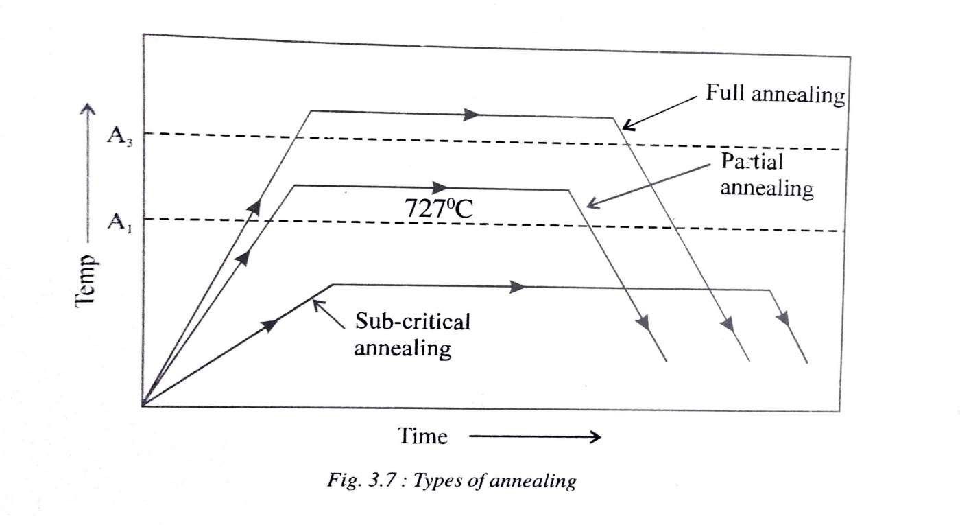
Annealing and Its Types
Annealing involves heating the specimen to the prescribed temperature, holding it at that temperature and then cooling it down to room temperature at a suitable slow rate. The important objectives of annealing are
i) Reducing hardness
ii) Improve machinability
iii) Facilitate cold workingby improving toughness
Types of annealing
1) Recrystallisation Annealing
|
Purpose |
To improve ductility To
remove strain hardening effects |
|
Temperature Range |
Above recrystallization temperature |
|
Holding Time |
2-3 minutes per mm of thickness |
|
Cooling Type |
Slow cooling |
|
Applications |
Steel wires, sheets and strips |
2) Full Annealing
|
Purpose |
To remove internal stresses, to improve ductility, for grain
refinement |
|
Temperature Range |
Above A3 temperature between 940°C
-960°C |
|
Holding Time |
Based on size and shape |
|
Cooling Type |
Very slow cooling. |
|
Application |
Hypo-eutectoid steels |
|
Disadvantage |
Expensive because of long
cooling cycle |
3) Partial Annealing
|
Purpose |
To improve machinability |
There are two step in the heat treatment procedure
Step 1
|
Temperature Range |
Heat to 940°-960°C |
|
Holding time |
Hold until complete austenite is obtained |
|
Cooling Type |
Rapid cooling
to below A1 temperature |
Step 2
|
Temperature range |
Hold at 600° - 700°C |
|
Holding time |
Hold until complete austenite is obtained |
|
Cooling Type |
Cooled in air. Rate of cooling is not important because once the temperature
is below A1 temperature, there will be no phase transformation for any rate of cooling |
|
Application |
Used for alloy steels |
|
Advantage |
Less expensive than full
annealing |
|
Disadvantage |
Not
suitable for heavy
components |
4) Process or Sub-Critical or Stress Relief Annealing:
|
Purpose |
To remove internal stresses To remove strain hardening effect and facilitate further cooling working |
|
Temperature Range |
Below A1 temp in the range of 650°-700°C |
|
Holding Time |
Sufficiently long |
|
Cooling Type |
Rate of cooling is not important because the temperature
range is below A1 temp and there will be no phase
transformation |
|
Applications |
Steel Wires, steel sheets and stampings |
5) Spheroidising Annealing:
Step 1
|
Temperature Range |
Below A1 temperature in the range of 650°C -
700° C |
|
Holding Time |
2-3 minutes per mm of thickness plus 40% more |
|
Cooling Type |
Slow cooling |
Step 2
|
Temperature Range |
Above and below
727°C (A1 temp) Alternative heating and cooling |
|
Holding time |
2-3
minutes/ mm of thickness + 40% more |
|
Cooling Type |
Slow cooling |
Step 3
|
Temperature Range |
750°C-780°C *for 0.8%
C steel) 780°-800°C (>0.8%C) |
|
Holding Time |
Hold till the
shape of carbides becomes spheroidal |
|
Cooling Type |
Furnace cooling (very slow) to below A1 temperature |
|
Applications |
High carbon steels, tool
steels, alloy steels
etc |
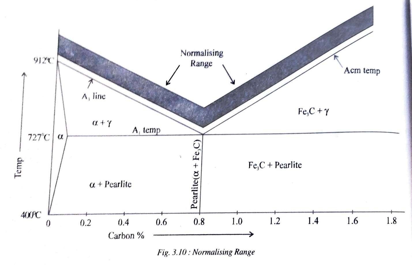
Normalizing
Normalizing consists of heating steels to about 40°C -50°Cabove upper critical temperature, holding it at that temperature for a short time and then cooling it in still air to room temperature. Cooling n still air is faster than the rate of cooling employed in annealing. That is the reason why normalizing is also called as air quenching.
The type of structure obtained by normalizing will depend largely on the thickness of cross section. Thin sections will give a much finer grain size than thick sections. The microstructure obtained after normalizing will generally be fine pearlitic. The purpose of normalizing is to produce a harder and stronger steel than annealing. Normalizing may also be used to improve machinability, modify and refine cast dendritic structure and grain refinement
Normalizing vs Annealing
|
Normalizing |
Annealing |
|
Fine pearlite is obtained |
Coarse and
medium pearlite is obtained |
|
Normalized steels are harder |
Less Harder |
|
Finer grain size |
Less finer |
|
Less expensive |
More expensive |
|
Cooling rates are not critical |
Cooling rates
are critical |
|
Improves machinability of medium carbon steels |
Improves machinability of low carbon
steels |
|
Normalized steels are less ductile |
More ductile |
Hardening
The heat treatment carried out on metals and alloys in order to increase their hardness is known as hardening.
Hardening involves heating to such a temperature to produce an austenitic structure, hold it at that temperature and quench (suddencooling by immersing) in water or oil,. By quenching, an extremely rapidrate of cooling is obtained.
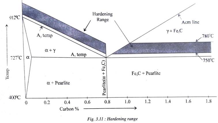
Fig 3.11 shows the hardening range for steels. Hypo-eutectoid steels (less than 0.8%C) are heated to about 30°-50°C above the critical temperature (A3 temperature) whereas eutectoid and hyper eutectoid steels are heated to about 30°-50°C above the lower critical temperature.
This means that the hardening range varies for hyper-eutectoid steels of varying carbon content whereas hyper-eutectoid steels are heated to about 30°-50°C above the lower temperatures. This is because a completely austenitic phase is ensured in hypo-eutectoid steels before quenching while in hyper eutectoid steels, only the pearlite phase is allowed to become austenite retaining the other phase cementite, before quenching.
Upon quenching, most of the austenite transforms into martensite in hypo-eutectoid steels whereas the microstructure of hyper- eutectoid steels have martensite and cementite.
HARDENABILITY
The hardenability of a metal alloy is the depth to which a material is hardened after putting it through a heat treatment process.
The hardenability of steel depends on
a) Composition of the steel and the method of manufacture
b) Quenching medium and the method of manufacture
c) Section (thickness) of steel
TEMPERING
Tempering is a process of heat treating, which is used to increase the toughness of iron-based alloys. Tempering is usually done after hardening.
The main objectives of tempering are:
i) To relive residual stresses
ii) To improve ductility, toughness, impact strength
iii) To reduce hardness
iv) To convert retained austenite
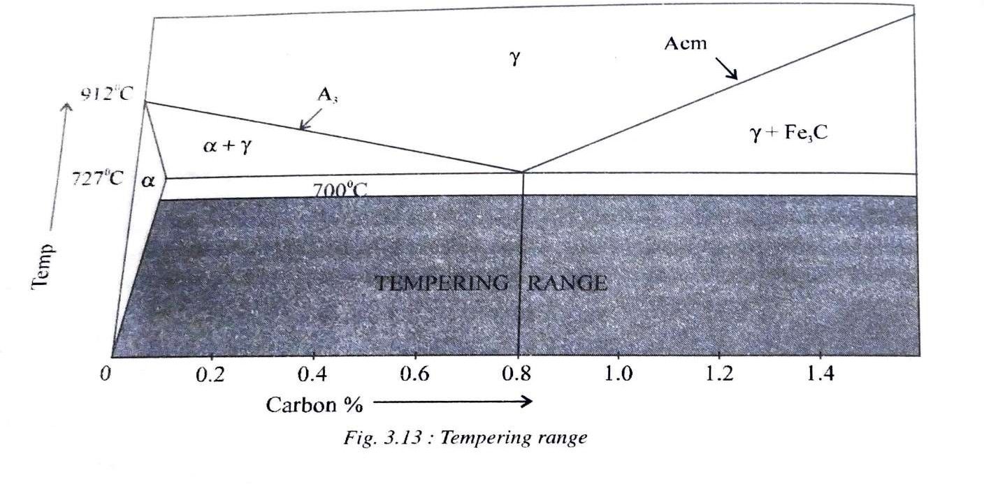
Fig 3.13 shows the subcritical temperature range of tempering heat treatment. Tempering however is carried out in three stages.
i) 150 -200°C:
Immediately after quenching, the specimen is heated in an oil bath to this temperature range is order to relieve the internal stresses and begin the decomposition of retained austenite. Excess carbon also starts precipitating out of martensite.
ii) 200-450°C:
Heating in this range increases the toughness at the expense of hardness,
iii) 450-700°C:
The fine cementite particles which has precipitated now joins together to form larger masses due to which steel becomes more ductile. A structure known as sorbite is obtained which has a coarse spheroidal structure at higher temperature
Austempering
Austempering is a type of cooling which is employed in order to obtain a 100% bainitic structure. A fully bainitic structure is less harder than the structure containing martensite but possesses a better impact resistance.
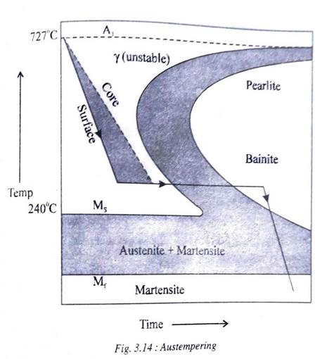
Fig 3.14 shows the TTT diagram on which is drawn the cooling curve, followed during austempering. A 100% bainitic structure is not possible to obtain by continuous cooling. Therefore steel is first quenched down to a temperature within the bainitic zone. It is then held at that temperature in a salt bath until the austenite is completely transformed into bainite.
After this the steel is allowed to cool to room temperature with the rate of cooling being immaterial. The dashed line in the figure shows that the core of the specimen to be austempered takes longer time to arrive at the bainitic zone than the surface.
MARTEMPERING
Martempering is a type of cooling which is employed in order to obtain a fully martensitic structure with a minimum of distortion and residual stresses in the specimen.
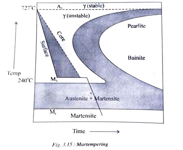
Here, the specimen is first cooled at a rate faster than the critical cooling rate to a temperature just above the martensitic start (Ms) temperature. It is held at this temperature in a salt bath sufficiently long to make the temperature uniform throughout the volume of the specimen but not long enough to transform into bainite. The specimen is then cooled in air to room temperature.
By air cooling, the martensite will be formed at nearly the same time throughout the specimen. Thus, martempering also minimizes residual stresses and reduces the danger of distortion and cracking.
CASE HARDENING
Carburizing
We know that the hardness of steel is increased with the presence of martensite in their microstructures. But the amount of martensite can increase only at higher carbon contents. In case of low carbon steels, the extent to which martensite is formed is reduced owing to lower carbon contents. In such cases, ore carbon is added to their surfaces. These steels whose surfaces are enriched in carbon are further subjected to regular hardening heat treatment as a result of which, more martensite forms at the surface and becomes more harder than in the interior. Carburizing is the term given to all methods of increasing the carbon content at surfaces.
There are three methods of carburizing – Solid, Liquid, Gaseous
Nitriding
Nitriding is the process of obtaining hard and wear resistant surface on components made from alloy steels which contain stable nitride forming elements such as aluminum, chromium, molybdenum, vanadium, tungsten and so on.
In this process the specimen is heated to a temperature of about 500°C and held for considerable duration in an atmosphere of gaseous nitrogen. Nitrogen is produced when ammonia gas passed through the furnace at 550°𝐶, the reaction being
2 NH3 ---> 2N + 3H2
This nascent nitrogen is readily absorbed into the surface of the steel. The holding time depends on the desired depths and size of specimens.
Cyaniding
In this process, steel surfaces are hardened by adding both carbon and nitrogen to the surfaces. The components to be case hardened are immersed in a liquid bath containing sodium cyanide and heated to the temperature range of 800-960°C.
The reaction which take place are,
2NaCN + 2O2 ---------- > Na2CO + 2N
2CO -------- > CO2 + C
The nascent nitrogen and carbon produced diffuse into the surface of the steel. Further the components are quenched in order to obtain a hard wear resistant surface with a relatively soft interior.
SURFACE HARDENING FLAMEHARDENING
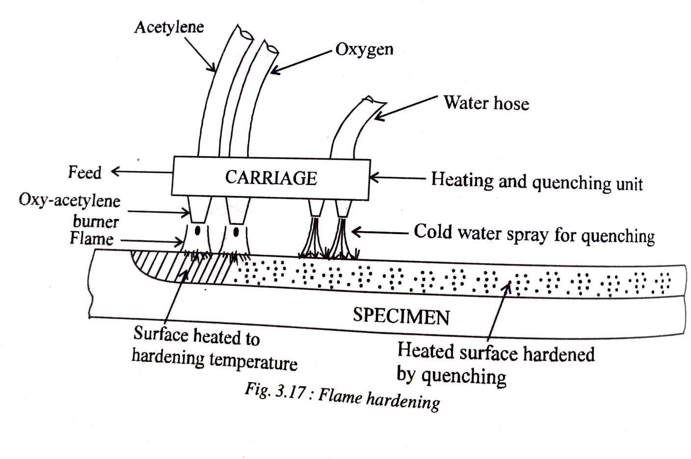
Flame hardening involves rapid heating of a steel specimen by means of an oxy-acetylene flame to the austenitic range and follow it by quenching. Only the surface gets highly heated and becomes austenitic and upon quenching becomes martensitic. Therefore the surface becomes very hard but the core remains tough.
The carriage in the flame hardening set-upas shown in fig 3.17 contains both heating and quenching units and can run along the length of the specimen. Depth of hardened zone may be controlled by adjusting the flame intensity, heating time and speed of travel of carriage.
INDUCTION HARDENING
Induction hardening involves heating of the surface of the component by electromagnetic induction. Here the specimen is passed throughinduction coils connectedto a high frequency alternating current generator.
When thigh frequency alternating current passes through the induction coils, a high-frequency magnetic field is set up. This magnetic field induces high frequency eddy currents and hysteresis currents in the specimen.
The metallicspecimen offers resistance to the passageof these currentsand hence get heated. The highfrequency induced currents tend to travel at the surface of the metal. This is known as skin effect.. Due to this, it is possible to heat a thin layer of steel without heating the interior. The surface layer is heated almost instantaneously which is quickly followed by quenching by spraying water on the surface of the specimen.
Ferrous and Non-Ferrous Materials
Cast Irons
Cast Ironsare those alloysof iron and carbon where the carbon content varies between 2.1% and 6.67%.However, since high carbon content tends to make the cast iron very brittle, most commercially availabletypes of cast irons are in the range of 2.5% to 4% carbon.
Types of Cast Irons
i) Gray cast irons
ii) Malleable cast Irons
iii) S.G iron
1. Gray Cast Iron
Gray Cast irons are the most widely used types of cast irons. They are distinguished by the presence of graphite in the form of flakes.Gray cast iron can be divided into different typesbased on the average length of the flakes in them.
The general characteristics of gray irons are:
|
Composition |
2.5% -4% carbon 1%-3% silicon, rest iron |
|
Microstructure |
𝛼-
ferrite and flake graphite’s |
|
Properties |
High fluidity, very
high compressive strength, very effective in damping vibrations, low cost. |
|
Fracture surface |
Greyish, blackish surface when fractured (because of
graphite flakes) Hence the name gray iron too |
|
Applications |
Pressure Vessels, cylinder heads, pistons, clutch plates, base
structure for machines, fittings, levers etc. |
2. Malleable Cast Iron
Malleable cast iron are hose alloys where almost all the carbonis in the free form in the shape of irregular particles known as temper carbon. As the name suggests, they are extremely malleable, and are producedby heat treatment of white cast iron.
The Characteristics of malleable iron are
|
Composition |
1.8% – 3.2% carbon 0.3% - 1.8% silicon, rest
iron |
|
Microstructure |
Dark graphite rosettes (temper carbon) in an 𝛼 – ferrite matrix |
|
Properties |
Highly malleable, very good machinability, good magnetic properties, wear resistance |
|
Applications |
Connecting rods, transmission gears, flanges pipe
fittings, differential cases
for automotive industry and marine
works |
3. Spheroidal graphite(SG) Iron
S.G Iron is characterized by the presence of free carbon in the shape of compact spheroids or nodules. S.G Iron is also very well known for its ductility. Hence the other names of SG iron are NodularIron or Ductile Iron.
|
Composition |
3% - 4% Carbon, 1.6 % -2.8% Silicon, rest iron Very low percentage of phosphorous and Sulphur |
|
Microstructure |
Dark graphite nodules surrounded by 𝛼 - ferrite matrix |
|
Properties |
Highly ductile, very
good machinability, high corrosion resistance and
good properties at elevated temperatures. |
|
Applications |
Flywheels, furnace doors,
wrenches, lathe chucks, motor frames, pump bodies etc. |
Non- Ferrous Alloys
Different typesof non-ferrous alloysare –
1. Copper and its alloys
2. Aluminum and its alloys
3. Magnesium and its alloys
4. Titanium and its alloys
Copper and its Alloys
The most important copperalloys can be classified as follows:
1. Brasses
a. Alpha brasses
a. Yellow alpha brasses
b. Red brasses
b. Alpha plus beta brasses
2. Bronzes
1. Tin bronzes ( Phosphor bronze)
2. Silicon bronzes
3. Aluminum bronzes
4. Beryllium bronzes
1. Brasses:
Brasses are essentially alloys of copperand zinc. But they may have small amount of other elementssuch as lead, tin or aluminum added to improve their properties.
1. Alpha Brasses
|
Composition |
Copper + up to 36%
zinc |
|
Microstructure |
Only solid solution 𝛼 – brass (FCC
structure) |
|
Properties |
High corrosion properties, suitable for cold working. |
|
Types of 𝛼 - brasses |
a)
Yellow 𝛼 -brasses b)
Red brasses |
|
Applications |
Bullet shots, military ammunition, automotive radiator core , storage
batteries etc. |
2. Alpha Plus Beta Brasses
|
Composition |
Copper + 38 - 46% zinc |
|
Microstructure |
Solid solution 𝛼 – brass
(FCC) Electron compound 𝛽 – brass(BCC) |
|
Properties |
Suitable for hot working, harder and more brittle at room
temperature than 𝛼 – brass and therefore difficult to cold – work. |
|
Types |
a)
Muntz metal b)
Naval Brass |
|
Applications |
Marine hardware, propeller shafts, condenser plates etc. |
2. Bronzes
Bronzes are those copperalloys which containup to approximately 12% of the principal alloying element.
1. Tin Bronzes (Phosphor bronzes)
|
Composition |
Copper 1-11% Tin +0.01-0.5% P |
|
Microstructure |
𝛼- phase and dark 𝛿- phase |
|
Properties |
High strength, toughness, low co-efficient of friction, free from
season cracking, high corrosion resistance |
|
Types of tin
bronzes |
a)
Admiralty gun metal b)
Bell metal |
|
Applications |
Bearings, steam pipe fittings, casting of bells |
2. Silicon Bronzes
|
Composition |
Copper+ up to 5%silicon |
|
Microstructure |
Single 𝛼-phase |
|
Properties |
Very strong, mechanical properties comparable to those
of mild steel, high corrosion resistance |
|
Applications |
Corrosion resistant
vessels, nuts and bolts, blades, bearings etc |
3. Aluminum Bronzes
|
Composition |
Copper+4-11% aluminum |
|
Microstructure |
Two phases primary 𝛼-phase, Eutectoid (𝛼 + 𝛾2 ) |
|
Properties |
Suitable for cold
working, good strength combined with corrosion resistance to atmosphere, and
water attack |
|
Applications |
Corrosion resistant vessels, nuts and bolts, blades, bearings, bushings etc. |
4. Beryllium Bronzes
|
Composition |
Copper + 1.5
-2% Be +0.2% Co |
|
Microstructure |
dark 𝛾 – phase at the grain boundaries of 𝛼 - phase |
|
Properties |
Excellent formability, good fatigue and creep resistance when hardened, high
electrical conductivity |
|
Applications |
Diaphragms, surgical instruments, bolts, firing pins etc. |
Aluminum and Its Alloys
1. Aluminum Copper Alloys:
|
Name of the alloy |
Duralium |
|
Composition |
Al + 4%
Cu |
|
Microstructure |
Solid solution 𝛼 – phase, intermediate phase Cu Al2 |
|
Properties |
One of the best non-ferrous alloys for age – hardening, high strength, corrosion resistant etc |
|
Applications |
Rivets in air craft construction, electrical cables, automobiles components etc |
2. Aluminum – Siliconalloys:
|
Composition |
up to 12.5% silicon |
|
Microstructure |
Solid solution 𝛼-phase + Eutectic (𝛼 + 𝛽 ) |
|
Properties |
Good forgeability, low co-efficient of thermal expansion, excellent castability and resistance to corrosion |
|
Applications |
Intricate castings, food – handling equipment, marine
fittings. |
3. Aluminum – Zinc Alloys:
|
Composition |
Up to 5.6%
Zn, 0.6% Mg 0.5% Cr, 0.2 % Ti |
|
Properties |
Above composition gives highest
mechanical properties without heat treatment. They have good castability, corrosion resistance and good machinability. |
|
Applications |
Aircraft structural parts,
turret housings, radio equipment |
4. Aluminum Magnesium alloys:
|
Composition |
Up
to 5% magnesium |
|
Properties |
Good weldability, good corrosion
resistance, moderate strength, poor casting properties |
|
Applications |
Architectural extrusions, tubing’s for automotive gas and oil lines,
fittings for chemical and sewage use etc. |
5. Aluminum Lithium alloys:
|
Composition |
Up
to 2.5% Lithium 1% Mg |
|
Properties |
Very low densities (2.5 to 2.6% g/cm3) excellent fatigue strength, low temperature, toughness, high specific modulus |
|
Applications |
Aircraft and aerospace industries |
MAGNESIUM ALLOYS
|
Composition |
Aluminum Zinc, Thorium, Zirconium are common alloying materials |
|
Properties |
i)
High strength to density
ratio ii)
Good resistance to
deformation at room
temperature |
|
Limitations |
i)
Magnesium ignites easily when heated in air. Hence difficult to cast. ii)
Relatively brittle because of HCP
structure iii)
Magnesium alloys have relatively low strength and poor resistance to creep fatigue and wear. iv)
Magnesium costs
more than Aluminum |
|
Applications |
i)
Steering wheels and columns, seat frames, transmission cases in automobiles. ii)
Handheld devices such as chain
saw, power tools etc. iii)
Audi-video computer
communications equipment’s such as laptops, camcorders, cellphones etc |
TITANIUM ALLOYS
|
Composition |
Aluminum, Tin, Vanadium, Molybdenum are common alloying elements |
|
Properties |
i)
High Strength for its
density ii)
Can be easily forged and machined iii)
Corrosion resistance at room temp
is extraordinary iv)
Retains strength at higher than
room temperatures |
|
Limitations |
i)
Chemically reacts
with other materials at higher temperatures ii)
Lower ductility because of HCP
structure iii)
More expensive than aluminum and
Magnesium |
|
Applications |
Air plane structure, space vehicles, surgical implants, Petroleum and Chemical industries etc |

