Material Science 3rd Module
Solidification
Solidification is the process where liquid metal transforms into solid upon cooling.
The properties of the solidified metal depends on its microstructure and the microstructure in turn depends on the ‘Solidification Mechanism’ employed to freeze the metal.
Transformation from liquid metal to solid metal is accompanied by a shrinkage in the volume. This volume shrinkage takes place in three stages:
(i) Liquid-Liquid
(ii) Liquid-Solid
(iii) Solid –Solid
Mechanism of Solidification in pure metals and alloys
Solidification of all liquid metals consist of two stages
A) Nucleation of minute Crystals
B) Growth of these crystals into grains
A) Nucleation:
This is the starting point of the solidification process of any metal or alloy. In this stage anumber of minutecrystals nucleate throughout the melt.
Metal in molten condition possesses high energy and the atoms have high mobility.
As the liquid metal cools, the atoms gradually lose their energy and their movements become less vigorous. Then when atoms collide with each other, attractive forces are set up and atomic bonds are reestablished between them.
Therefore, small cluster of atoms, usually consisting of 10 –15 atoms are formed at several places in the molten metal and are known as nuclei.
It is the number of nuclei formed during the stage of nucleation which decides the final grain structure of the solidified metal and therefore some of its properties.
Nucleation in metals and alloys may occur by two mechanisms namely
(i) Homogenous Nucleation (ii) Heterogeneous nucleation
B) Crystal Growth:
This is the stage where molten metal continues to solidify around the nuclei which are already formed. The nuclei and the metal solidifying around them continuously release latent heat which it had acquired during melting. This heat is absorbed by the surrounding molten metal and therefore for solidification to continue more and more heat has to be extracted I.e., cooling of metals should continue.
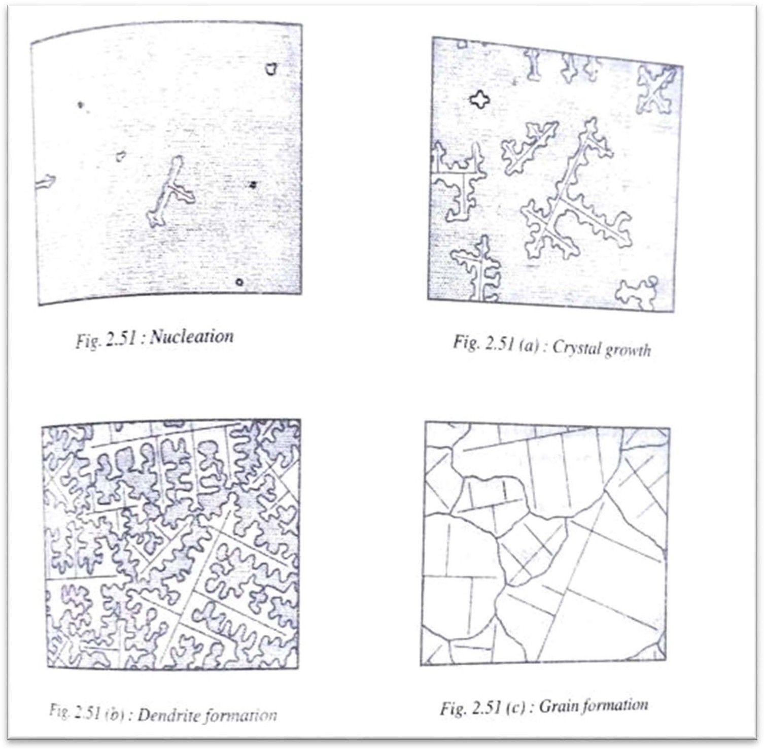
As the temperature decreases due to cooling the nuclei grow rapidly with atoms attaching themselves in identical layers around the nuclei grow rapidly with atoms attaching themselves in identical layers around the nuclei and a dendritic formation takes place.
When more and more atoms attach themselves in a particular direction, they form a trunk like that of a tree. Out of this trunk branches grow out and from these branches some more smaller branches grow out perpendicularly and altogether forms a tree like structure. This type of grow this called the dendritic growth(fig 2.51 a and b)
The dendrites are like skeleton in the microstructure of the solidified metal. When one big dendrite tree meets another, a grain boundary is formed along their border while the dendrites themselves become grains or crystals (fig 2.51c). The liquid metal along the grain boundaries will be the last to solidify and this marks the end of solidification.
Solidification of Alloys
An alloy is defined as a combination of two or more elements of which at least one of them is a metal and the resulting material should have metallic properties.
Ex: Steel, Cast Iron, Brass, Bronze etc.
Solidification in alloys take place in the same two stages i.e., Nucleation and crystal growth. But most alloys, with some exceptions, solidify over a range of temperatures rather than at a constant temperature as in pure metals.
Based on solidification ranges, alloys can be divided into those which:-
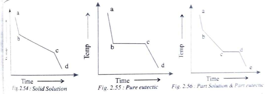
i) Begin solidification at one temperature and end at another temperature I.e., solidify over range of temperature (fig 2.54).
E.g.: Solid-solution alloys.
ii) Begin and end solidification at a constant temperature just like inpure metals (fig 2.55). E.g.:Pure eutectics
iii) Begin solidification like a solid – solution but end it like a eutectic I.e., the first half of the solidification is over a range of temperatures and the second half is at a constant temperature (fig 2.56)
Homogeneous Nucleation
When nucleation takes place in a liquid metal without the help of any impurities, then it is known as homogeneous nucleation.
Homogeneous nucleation occurs in perfectly homogeneous materials such as pure liquid metals.
It is the occurrence of ordered group of 100-200 atoms forming smallclusters called nuclei.
For each nucleus so formed to be stableand to grow into a crystal,it must reach a certainsize, called the ‘Critical Size’ or ‘Critical radius’.
When solidification takes place, latent heat (Δfv)is released by the solidifying atoms.
This is given by,

Where r = radius of the nucleus formed
ΔG = latent heat energy released / unit volume(Negative sign because heat is released)
Whenever a new surface is formed, an energy known as surface energy is associated with it. In the melt, the surface energy associated with the newly formed nucleus is given by the relation,
Δfs = 4πr2s𝛾 --- (2)
Where r = radius of the nucleus, 𝛾= surface energy / unit area (positive because heat is absorbed)
Thus, the net energy change for a particle is of radius r is given by, Δf - Δfv + Δfs
ΔG+4πr 𝛾----- (3)
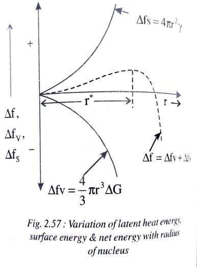
Fig shows the relationship of latent heat energy (Δfv) and the surface energy (Δfs) with increase in the radius of the nuclei. It is also clear from the fig that as the particle radius increases, the net free energy (Δf) also
increases till the nucleus reaches a critical radius r but with further increase in particle radius the free energy decreases and even becomes negative. In order for the grain growth to take place around a particular nucleus, it should have reached the critical radius
The size of the critical radius can be estimated by differentiating Equation (3) with respect to ‘r’ and equating to zero


The net energy change for radius r* is given by substituting value of r* in equation3


Therefore

where Δf* is also known as activation energy
Heterogeneous Nucleation
When nucleation takes place in liquid metal with the help of impurities, then it is known as heterogeneous nucleation.
Impurities could be insoluble matter like sand particles, alloy additions to the solidifying metal, even mould walls or any other foreign agent deliberately added to bring about nucleation in order to begin the process of solidification.
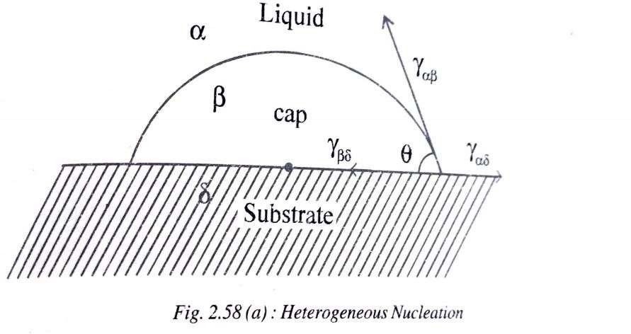
Nuclei in heterogeneous nucleation are formed on the surfaces of the above possible surfaces often called the substrate. But for nucleation to actually take place I.e., for a particular surface to serve as a nucleation site for that system, two things must happen
(I) The substrate surface must be actually wetted by the liquid metal. Imagine surfaces like plastic which do not get wetted by water particles which fall on them, and hence do not hold them.
(ii) The contact angle (𝜃) of the cap-shaped nucleus should be less than 90° theoretically. In general, all liquid particles resting on flat or circular surfaces and wetting them will yield angles less than 90°.
Cast Metal Structures or Ingot Structures
When Molten metal is poured into a mould and allowed to solidify, different gain structures may result in the casing.
In other words, the size and shape of the grains or crystals may differ for each casting and this depends on several factors like
a) Pouring temperature.
b) Mould material and its thermal conductivity
c) Mass of metal
d) Composition of the alloy
Basically, there are three types of grain structures which can result in ingot castings. They are:
i) Columnar grains
ii) Equiaxed grains
iii) Partially Columnar and Partially equiaxed
i) Columnar Grains:
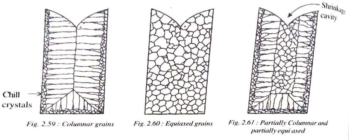
When molten metal is poured into a mould, the layer which comes in contact with the mould walls cools first and forms fine, hard crystals known as chill crystals. The liquid adjacent to these chill crystals then solidify and start growing in a direction opposite to the direction of heat flow and become columnar grains (fig 2.59). This occurs when there is an absence of nucleation at the centre of the melt and is typical of pure metals.
ii) Equiaxed grains:
Equiaxed grains are obtained when liquid metal which is poured into the mould is cooled suddenly. This type of structure occurs when there is extensive nucleation throughout the melt.
Fig 2.60 illustrates equiaxed grains and is typical of alloys.
iii) Partially Columnar and partially equiaxed:
The solidification here begins like a pure metal and ends like an alloy. In other words solidifications begins with chill crystals and growth of columnar grains but before they advance nucleation takes place at the centre and results in equiaxed grains and is typical of solid-solutions alloys (fig 2.61)
Grain Refinement
Grain refinement is nothing but modifying the size of equiaxed grains in a casting.
Generally, grain refinement refers to decreasing the average grainsize. This can be brought about by a number of following ways: -
i) When the rate of cooling is high.
ii) Low pouring temperature
iii) Proper control of alloying elements to promote constitutional super cooling
iv) Addition of an inoculating agent in the form of a metal powder to the melt while it is being poured
v) When thermal conductivity of the mould is high.
Solid Solutions
A solid solution is simply a solution in the solid state and consists of two kinds of atoms in one type of small lattice. In a solid solution, the metal in the major proportion is called the solvent and the metal in the minor proportion is called the solute.
E.g., Cu-Ni, Au-Ag etc.
Types of Solid Solutions
1) Substitutional solid solutions
2) Interstitial Solid Solutions
1) Substitutional Solid Solution:
In this type of solid solution, the solute atoms substitute the atoms of the solvent in the crystal structure of the solvent. For example in the Au-Ag solid solution, the silver atoms substitute for the gold atoms in the FCC structure of gold. There are two types of substitutional solid solutions.
a) Orderly Substitutional solid solution:
In this type, the solute atoms substitute the solvent atoms in an orderly manner, taking up the fixed positions of symmetry in the lattice.
Therefore this type of solid solution has an uniform distribution of solute and solvent atoms.
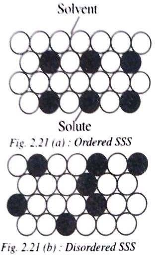
b) Disordered substitutional solid solution: The solute atoms here do not occupy any fixed positions but are distributed at random in the lattice structure of the solvent.
In this type of solid solution, the concentration of solute atoms
may vary considerably through out the lattice structure
It is to be noted ere that substitutional solid solutions are generally ordered at lower
temperatures and disordered at higher temperatures, thus temperature being the deciding factor.
Interstitial Solid Solution
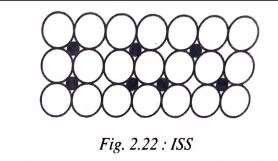
These are formed when atoms of small atomic radii fit into the interstitial spaces of the large solvent atoms.
Atoms of elements such as carbon, nitrogen, boron, hydrogen which have very small atomic radii (less than IÅ) are likely to form interstitial solute atoms and may dissolve more readily in transition metals such as Fe, Ni, Mn, Cretc. than in other metals
For example carbon forms an interstitial solid solution with FCC iron and is called austenite,
Interstitial solid solutions normally have limited solubility and generally are of less importance than substitutional solid solutions with austenite being an exception.
Rules of Formation of Solid Solutions Or HUME-ROTHARY Rules
These rules govern the formation of substitutional solid solutions. In other words, only when these rules are satisfied, a substitutional solid solution can form.
1) Crystal Structure Factor:
For complete solid solubility of two elements, they should have the same type of crystal lattice structure.
For example in Au- Ag solid solution, both have FCC structure
2) Relative Size Factor:
The atoms of the solute and the solvent should have the same atomic size approximately, This factor is satisfied if the difference in the atomic radii of the two elements is less than 15%.
3) Chemical -affinity factor:
For a substitutional solid solution to form, the two metals should have very less chemical affinity. Greater the chemical affinity between the two metals, lesser are the chances of forming a solid solution. Generally, the farther apart the elements are in the periodic table,the greater is their chemicalaffinity.
4) Electro-negativity :
The above point can also be explained in terms of electro negativity (tendency to acquire electrons) of the two elements. Higherthe electro-negativity of the two elements, greaterwill be the chances of forming an intermediate phase rather than a solid solution.
5) Relative valence factor:
Among two metals which have satisfied all the above rules, the metal with thelower valency tendsto dissolve more of a metal of higher valency than vice-versa.
For example in the Al-NI alloy system, both metals are faced centred cubic and their relative size difference is less than 15%.
However, Nickel which has a valency of two dissolves 5% aluminum, while on the other hand aluminum which has a valency of three dissolves only 0.004% Ni.
Intermediate Phases or Intermediate Alloy Phases
Addition of an alloying element to a given metal to an excessive amount than solid solubility results in a second phase appearance with the solid solutions. This second phase is known as Intermediate Alloy Phase.
It differs in both crystal structure and properties from solid solutions
Intermediate phase may range between ideal solid solutions on one hand and ideal chemical compounds on the other hand
Intermediate alloy phases could be either intermediate solid solutions or intermediate compounds.
The three most common intermediate alloy phases are:
1) Intermetallic or valency compounds
When intermediate alloy phases are exclusively metal-metal systems, they are called intermetallic compounds.
These compounds are generally formed between chemically dissimilar metals and are combined by following the rules of chemical valence.
The combination is usually non-metallic and show poor ductility and poor electrical conductivity and may have a complex crystal structure.
E.g., Mg2Pb, Mg2Sn.
2) Interstitial compounds
These are similar to interstitial solid solutions except that they have more or less a fixed composition.
E.g.: Fe2C, Tic.
The interstitial compounds are metallic in nature, have high melting points and are extremely hard. Most carbides are interstitial in nature.
3) Electron Compounds
These compounds are of variable composition and do not obey the valency law, but have a definite electron to atom ratio
For example in the compound Cu9Al4, each atom f copper has one valence electron and each atom of aluminum has three valence electrons, so that 13 atoms which make up the compound have 21 valence electrons to atom ratio 21:13.
Many Electron compounds have properties resembling those of solid solutions including a wide range of compositions, high ductility and low hardness.
Gibb’s Phase Rule
It states that, P+F = C + 2 Where,
· P = number of phases
· F = number of degrees of freedom
· C = number of components in the system
· Digit 2 = the two system variables, temperature & pressure (A pnemonic for Gibb’s Phase rule would be; Police force=Cops +2)
Phase: A Phase is a homogeneous, physically distinct portion of a system having its own boundary. A solid phase has ts own crystal structure and its set of individual properties
Degrees of freedom: The number of degrees of freedom of a system is the number of variables that may be charged independently without causing the disappearance of a phase.
In other words, the equilibrium of the system is not disturbed by altering the variable. These variable may be external (temperature ) and internal(composition).
LEVER RULE
The amount or the quantity of each phase present at M is given by the Lever Rule. It states that, “The relative amount of each phase is directly proportional to the length of the opposite lever arm”.

A mechanical analogy to the ‘Lever Rule’ is shown in fig 2.26.
Consider a lever of length OP equal to the length of the tie line. A fulcrum is considered to be supporting the lever. A fulcrum is considered to be supporting the lever at point M which represents the overall composition. In order to keep the lever horizontal i.e., in equilibrium, weights are hung at ends ‘O’ and ‘P’ which are proportional to opposite lever arms. In other words WL represents
the weight or the amount of liquid phase and Ws represents the weight or th amount of solid phase present at.
Phase Diagrams
A Phase diagram is essentially a graphical representation of an alloy system. Phase diagrams are also called as Equilibrium diagrams.
Phase Diagrams are classified as:
I) Unary phase diagram (one component)
II) Binary phase diagram (two component)
III) Ternary phase diagram (three component)
Binary Phase Diagrams
A binary phase diagram is drawn with temperature on Y axis and various compositions of the two components on the X-axis. Pressure is assumed to be constant at 1 atm for all binary phase diagrams.
Fig 2.23 shows the phase diagram of Ni-Cu system which forms a solid solution for its complete range of compositions.
For all combinations of temperature and compositions above the curve marked liquidus, the mixture is in the liquid state. For all combinations below the solidus curve, the mixture is in the solid state and then we have a mixture of solid and liquid for any combinations between the two curves.
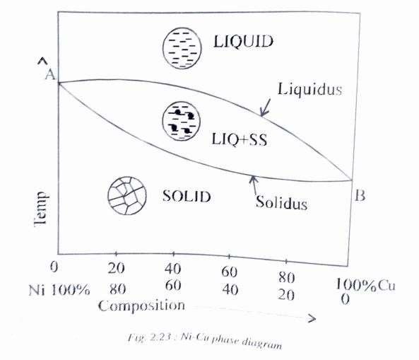
Points A and B represent the melting temperatures of nickel and copper, respectively.
It is to be noted here that phase diagrams show the relationship of the phases with temperature and composition will not change with time. Equilibrium conditions may be approached by extremely slow heating and cooling, so that if a phase change is to occur by varying temperature or composition, sufficient time must be allowed.
CONSTRUCTION OF PHASE DIAGRAMUSING COOLING CURVES
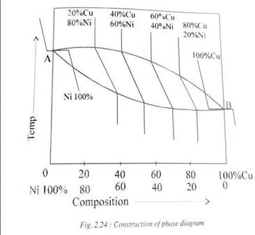
Following are the general steps involved In the construction of a binary equilibrium diagram between any two metals. The example taken here is the Nickel-Copper system which forms a continuous solid solution(Fig 2.24)
1. Cooling curves of pure Nickel and pure Copper are drawn on two parallel vertical axes which represent temperatures.
2. A series of cooling curves of different compositions of Ni and Cu are drawn at appropriate places between the cooling curves of the two pure metals.
3. The cooling curves of all the alloys are typical that of a solid solution i.e., there is liquid-liquid, liquid-solid and solid-solid transformations which make up each cooling curve.
4. Now, a curve is drawn which joins the beginning of solidification points of all the cooling curves of the alloys. A curve is also drawn which joins the end of solidification of all the cooling curves
5. In the cooling curves of pure metals Ni and Cu the mid points are chosen for both beginning and ending of solidification to join the two curves since they are at constant temperatures.
6.Therefore an equilibrium diagram is obtained which is normally shown without the series of cooling curves which helped its construction
