Material Science 4th Module
Composite Materials
Composite materials are those which are created artificially by combining two or more materials which usually have dissimilar characteristics.
In other words, a composite material can be defined as a ‘materials system composed of a combination of two or more constituents that differ in form and chemical composition and which are insoluble in each other’.
Role of matrix
1. Matrix transfers the applied load to the reinforcement
2. Matrix protects the reinforcement from mechanical and environmental attacks.
3. Matrix provides for low density in case of FRP
4. Matrix improves the impact and fracture resistance of composite
5. Matrix enables to keep the fibres aligned in a pre-determined direction
Role of Reinforcement
1. Reinforcement gives strength and stiffness to the composite
2. Reinforcement helps engineers in tailoring composites to the needs of specific applications
3. Reinforcements helps in obtaining properties in composites in the direction preferred
4. Reinforcement deflects crack front in matrix thereby hindering crack growth
Classification of Composites
Composite materials can be classified in two ways depending on the base matrix material used or depending on the shape of reinforcement used
According to Base – Matrix material
i) Polymer composites
ii) Ceramic composites
iii) Metal- matrix composites
According to shape of reinforcement
i) Fibre / Whiskers
ii) Laminate
iii) Particulate
Types of Matrix Materials
i) Polymer – Matrix Composites (PMC’s)
Polymer matrix composites (PMC’s)consist of a polymer resinas the matrix material. The term resin is used in the context to denote a high -molecular weight reinforcing plastic.
These materials are used as matrix materials in great diversity of composite applications, as well as in large quantities because of their excellent room - temperature properties, ease of fabrication, highly economical costs and aesthetic values.
Polymer matrices are often dispersed with the reinforcement material in the shape of fibres which are normally stronger and have a higher melting temperature.
Thermoplastic polymers and thermosetting polymers are both used extensively as matrix materials.
ii) Ceramic Matrix Composites (CMC’s)
Ceramic materials are very well known for their high temperature properties as well as their resistance to oxidation. But they are very brittle which limits their applications.
Ceramics which are commonly used as matrix materials are silicon nitrade (SI3N4), Silicon Carbide(SiC), Alumina(Al2O3), Zirconium dioxide (ZrO2) but it is a fact that ceramics make better reinforcement material than matrix materials.
iii) Metal -Matrix composites (MMC’s)
Metal – matrix composites are those where metals or alloys are used as matrix materials, as the name implies. Metals used are usually ductile in mature and is reinforced with stronger and low-density materials of all shapes -fibres whiskers and particulate.
Such combinations help in obtaining materials with improved stiffness, abrasion resistance, creep resistance, thermal conductivity and dimensional stability.
Some of the advantages of metal – matrix composites include higher operating temperatures, non-flammability and greater resistance to degradation by organic fluids. But MMC’sare more expensive than PMC’s and therefore, their use is somewhat restricted.
Examples for MMC’s include aluminum-alloy matrix reinforced with alumina and carbon fibres used in automobiles as engine components.
|
Thermo plastic polymers |
Thermo setting polymers |
|
1. They have
long chain polymers held by secondary bonds |
They have 3-D network of bonds |
|
2. Polymerization is linear |
Polymerization proceeds in all directions |
|
3. They soften
when heated and
harden when cooled |
They become permanently hard when
they are heated and do
not soften upon cooling |
|
4. At higher
temperatures, these polymers liquify because of the breaking of secondary bonding forces. |
At higher temperatures, the strong cross-linked bonds are broken and leads to polymer
degradation rather than melting |
|
5. They are relatively sold and ductile |
They are harder, stronger and brittle |
|
6. Suitable for use only
at low temperatures. |
Suitable at both low
and high temperature |
|
7. Examples – nylons, PTFE,
Polythene |
Examples include
epoxies, phenolics, polyesters etc., |
|
8. Applications – toys, bearings, cans, flexible bottles, safety helmets |
Applications – electrical moldings, sinks, motor housings, telephones, helmets, chairs
etc. |
Types of Reinforcement
i) Fibre Reinforced Composites
Fibre reinforced composites are those where the reinforcement is in the form of fibres. A natural example for a fibre reinforced composite is wood in which strong cellulose fibres are aligned in a base matrix of lignin which binds the fibres
Technologically the most important type of composites is fibre reinforced ones because of their wide range of applications. The characteristics of fibre reinforced composites are expressed in terms of specific strength and specific modulus parameters.
Fibre reinforcements can be employed in all three types of matrices i.e, plastic ceramic and metal. Usually, a fiber reinforced composite contains high strength and low density fibres in a ductile matrix. However, the combination as a composite can have reasonable strength and good toughness and can still have low density.
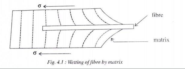
The matrix binds the fibres together and protects them from mechanical and chemical damage. The strength of the fibre reinforced composite is determined by the strength of the fibre and the strength of the bond between the fibres and the matrix.
The bond between the fibres and matrix must be strong enough to prevent the fibre pullout under external loads (Fig 4.1), For this to happen the matrix should actually wet the fibres and at the same time there should be no chemical reaction between them.
ii) Laminated Composites
In fibre -reinforced composites, if the fibres are of uniform alignment, the composites show anisotropic properties i.e., different properties along different directions. Bit if layers of such composites are stacked and bonded together in such a way that successive layers have their fibres aligned in different directions, the composite overall will have high strength and uniform properties in all directions.(Fig 4.5)
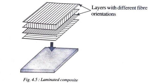
The best example for a laminated composite is plywood where successive layers of wood having different orientation of grains are cemented together and the composite on the whole has better strength in all directions.
Laminated composites can also be made from layers of two different materials that are bonded or cladded together.
iii) Particulate Reinforced composites
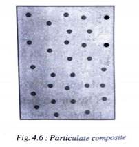
In this type of composites, particles of varying shape and size of one material is dispersed in a matrix of second material.
Particulate composites are similar in construction to dispersion strengthened alloys but differ in particle size and percentage by volume.
Particulate composites ae produced with all thee types of matrix materials. Important among them are “Cermets” which are a group of ceramic- metal combination materials.
Advantages Limitations and Applications of Composite Materials
Advantages
1. Composite materials possess an excellent combination of mechanical, chemical structural, optical and other desired properties
2. They are generally light weight materials having higher strength to weight ratio and higher modulus to density ratio than the conventional materials.
3. Composites, especially the polymer matrix composites can be moulded to any shape and size
4. They possess excellent anti corrosion and anti-chemical properties
5. They also have good resistance towards severe climatic conditions like heat, cold or rains.
6. Fibre-reinforced composites are virtually replacing every object made of conventional materials due to its low cost and ease of production
7. Wastage can be reduced in the fabrication of composites. Recycling is also possible in many cases.
8. Composites can be designed to obtain aesthetic appearance
Limitations
1. Polymeric composites are not suitable for high temperature applications.
2. They have low flash and fire points
3. Cost of composites is higher when volume of production is less
4. On prolonged exposure to sunlight, the colors of composites generally fade out
Applications of Composite materials
1. In automobile industries (e.g.,Steel and Aluminumbody)
2. Marine applications like shafts, hulls,spars (for racingboats)
3. Aeronautical application like components of rockets, aircrafts (buisness and military), missiles etc.
4. Communication antennae,electronic circuit boards(e.g., PCB, breadboard)
5. Safety equipment’s like ballistic protection and Air bags of cars
What is FRP? (Fiberglass reinforced polymer)
FRP (Fiberglass reinforced polymer) is a stronglight weight buildingthat resist corrosion
Open MouldingProcesses
Spray Lay-Up
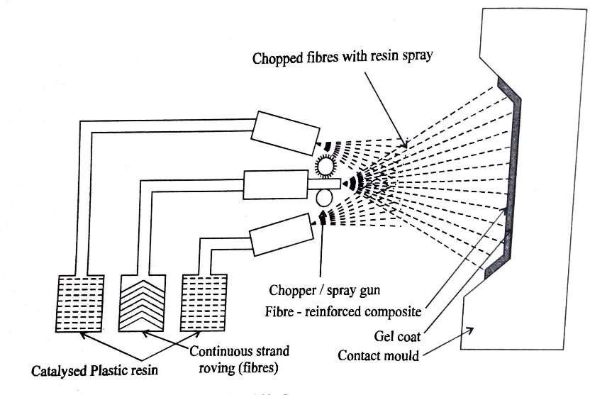
Description:
In this process, continuous fibres are first cut into desired length by a chopper. Then a mixture of fibre and resin along with a catalyst is sprayed simultaneously onto a vertical mould. The density of the deposited laminate is later increased with the help of a roller onto a vertical mould. The density of the deposited laminate is sure that the resin completely covers the reinforcing fibres. Multiple layers may be added to produce the desired thickness. Curing is usually at room temperature but may be accelerated by the application of a moderate amount of heat.
Material Options:
· Resins: Primarily polyester
· Fibres: Glass roving only
· Cores: None. These have to be incorporated separately
Typical Applications:
Simple enclosures lightly loaded structural panels, e.g. caravan bodies, truck fairings, bathtubs, shower trays, some small dinghies.
Main Advantages
· Widely used for many years.
· Low-cost way of quickly depositing fibre and resin.
· Low-cost tooling.
Main Disadvantages:
· Laminates tend to be very resin-rich and therefore excessively heavy.
· Only short fibres are incorporated which severely limits the mechanical properties of the laminate.
· Resins need to be low in viscosity to be sprayable. This generally compromises their mechanical/thermal properties.
· The high styrene contents of spray lay-up resins generally mean that they have the potential to be more harmful and their lower viscosity means that they have an increased tendency to penetrate clothing.
Limiting airborne styrene concentrations to legislated levels is becoming increasingly difficult
Wet/Hand Lay-up
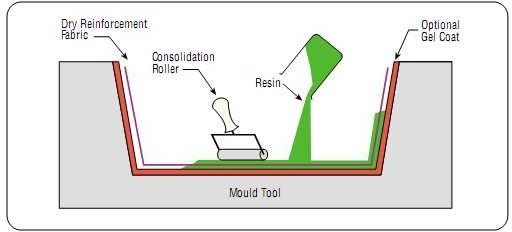
Description:
Resins are impregnated by hand into fibres which are in the form of woven, knitted, stitched or bonded fabrics. This is usually accomplished by rollers or brushes, with an increasing use of nip-roller type impregnators for forcing resin into the fabrics by means of rotating rollers and a bath of resin. Laminates are left to cure under standard atmospheric conditions.
Materials Options:
· Resins: Any, e.g., epoxy, polyester, vinylester, phenolic
· Fibres: Any, although heavy aramid fabrics can be hard to wet-out by hand.
· Cores: Any.
Typical Applications:
Standard wind-turbine blades, production boats, architectural mouldings.
Main Advantages:
· Widely used for many years.
· Simple principles to teach.
· Low-cost tooling, if room-temperature cure resins are used.
· Wide choice of suppliers and material types.
· Higher fibre contents and longer fibres than with spray lay-up.
Main Disadvantages:
· Resin mixing, laminate resin contents, and laminate quality are very dependent on the skills of laminators. Low resin content laminates cannot usually be achieved without the incorporation of excessive quantities of voids.
· Health and safety considerations of resins. The lower molecular weights of hand lay-up resins generally mean that they have the potential to be more harmful than higher molecular weight products. The lower viscosity of the resins also means that they have an increased tendency to penetrate clothing.
· Limiting airborne styrene concentrations to legislated levels from polyesters and vinylesters is becoming increasingly hard without expensive extraction systems.
· Resins need to be low in viscosity to be workable by hand. This generally compromises their mechanical/thermal properties due to the need for high diluent/styrene levels.
Vacuum Bagging and Pressure bag Moulding
Description:
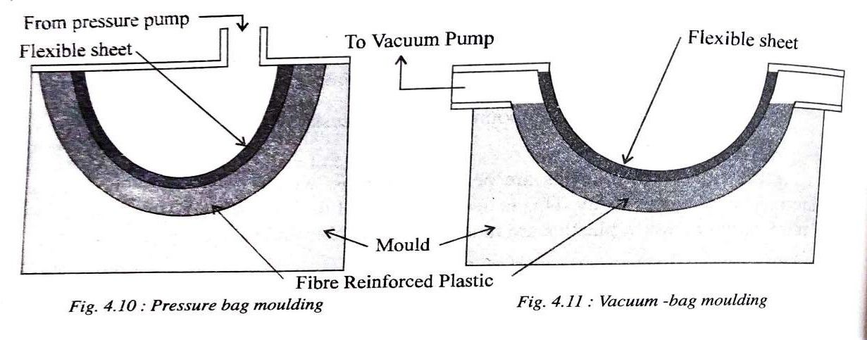
Bag moulding is an improvement over the hand lay-up process in that it further removes the entrapped air. The two-basic bag moulding methods are Pressure – bag,Vacuum – bag.
In all the different types of bag moulding, plastic resin is first poured over fibre reinforcement mats placed in an open mould. This mixture of fibre and resin is covered by a flexible sheet. Pressure is then applied to the sheet in various ways so as to compact the fibre and matrix composite. In the case of (i) pressure bag moulding high pressure air is used to compact the mixture in the mould cavity.
In (ii) Vacuum- bag moulding a vacuum evacuate the mould cavity. The vacuum created results in the elimination of voids, trapped air and excess resin and at the same time has a compacting effect
Materials Options:
· Resins: Primarily epoxy and phenolic. Polyesters and vinylesters may have problems due to excessive extraction of styrene from the resin by the vacuum pump.
· Fibres: The consolidation pressures mean that a variety of heavy fabrics can be wet-out.
· Cores: Any.
Typical Applications:
Large, one-off cruising boats, race car components, core-bonding in production boats.
Main Advantages:
· Higher fibre content laminates can usually be achieved than with standard wet lay-up techniques.
· Lower void contents are achieved than with wet lay-up.
· Better fibre wet-out due to pressure and resin flow throughout structural fibres, with excess into bagging materials.
· Health and safety: The vacuum bag reduces the amount of volatiles emitted during cure.
Main Disadvantages:
· The extra process adds cost both in labour and in disposable bagging materials.
· A higher level of skill is required by the operators.
· Mixing and control of resin content still largely determined by operator skill
Filament Winding:
Description:
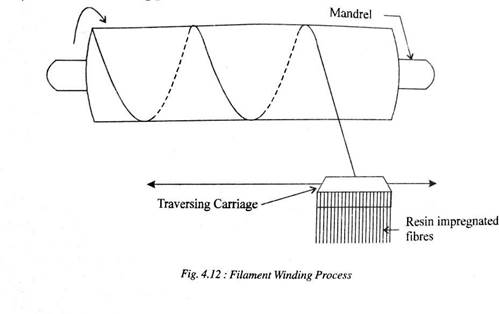
In this process, strands of fibre reinforcement is fed through a plastic resin bath and then wound on a suitable rotating mandrel in pre-determined orientations. While the mandrel rotates and rolls up the resin impregnated fibres, the traversing carriage runs along the length of the mandrel. The filaments are wound along different orientations so as to utilize their strength in an effective manner.
When sufficient layers have been taken up, the wound mandrel is either cured at room temperature or at an elevated temperature in an oven. The molded composite is then stripped from the mandrel. In some cases the mandrels are usually made of low – melting point alloys and are later melted down.
Materials Options:
· Resins: Any, e.g., epoxy,polyester, vinylester, phenolic
· Fibres: Any. The fibres are used straight from a creel and not woven or stitched into a fabric form
· Cores: Any, although components are usually single skin
Typical Applications:
Chemical storage tanks and pipelines, gas cylinders, fire-fighters breathing tanks
Main Advantages:
· This can be a very fast and therefore economic method of laying material down.
· Resin content can be controlled by metering the resin onto each fibre tow through nips or dies.
· Fibre cost is minimised since there is no secondary process to convert fibre into fabric prior to use.
· Structural properties of laminates can be very good since straight fibres can be laid in a complex pattern to match the applied loads.
Main Disadvantages:
· The process is limited to convex shaped components.
· Fibre cannot easily be laid exactly along the length of a component.
· Mandrel costs for large components can be high.
· The external surface of the component is unmoulded, and therefore cosmetically unattractive.
· Low viscosity resins usually need to be used with their attendant lower mechanical and health and safety properties.
Closed Moulding Process
Pultrusion Process:

Pultrusion process is used for producing fibre reinforced plastics of constant cross section such as I- beams, tubes, pipes etc. In this, resin impregnated fibres are first fed into a pre – forming box which gives appropriate orientation to the fibres. These oriented fibres are then fed into a heated steel die which determines the cross section of the composite stock. Thus, continuous lengths of constant cross section can be drawn through the die. Very high strengths in certain directions are possible in the composites because all the fibres run parallel to the length of the stock. A high volume fraction of fibres can be packed into the composite which also contributes to the high strength.
Advantages:
o The process is suitable for mass production.
o The process is fast and economic.
o Resin content can be accurately controlled.
o Fibre cost is minimized as it can be taken directly from a creel.
o The surface finish of the product is good.
o Structural properties of product can be very good as the profiles have very straight fibres.
Disadvantages:
o Limited to constant or near constant cross-section components.
o Heated die costs can be high.
o Products with small cross-sections alone can be fabricated.
Applications:
Beams and girders used in roof structures, bridges, ladders, frameworks
Pulforming
In this process,the fabrics may also be introduced into the die. The fabrics provide a fibre directionother 0°. Further, a variant of this method to produce a profile with some variation in the cross-section is available. This is known as pulforming.
Injection Molding
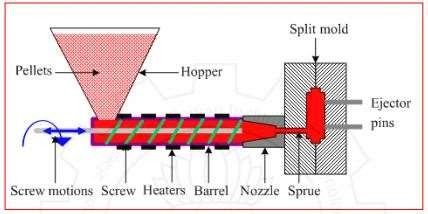
In this process, plastic granules are heated and forced under pressure into a die cavity of desired shape. This process is well suited for producing true three-dimensional shapes such as bottles, toys etc., which require fine details like holes, snaps, and surface details. Figure 3.7.2 schematically present san Injection Moldin gset-up for polymer processing.
Design for gating and feed system for the die is crucial to ensure complete die fill. It is important to design the molding so that solidification does not prevent complete mold filling. The design and location of the gates for entry of polymer is a crucial design details. For large part more than one gate may be required for proper flow of material.
Mold must be designed in such a way that the solid part can be ejected without distortion. By considering proper orientation at the beginning, in may be possible to avoid expensive mold cost. If possible, design the part so that it can be ejected in the direction of mold closure.
To minimize the shrinkage fillers like glass fiber, wood flour, are added during molding. With some part geometries, post mold shrinkage can lead to generation of high residual stress.
Thermoforming Process
Thermoforming is a manufacturing process where a plastic sheet is heated to a pliable forming temperature, formed to a specific shape in a mold, and trimmed to create a usable product. The sheet, or "film" when referring to thinner gauges and certain material types, is heated in an oven to a high- enough temperature that permits it to be stretched into or onto a mold and cooled to a finished shape.

1- The plastic sheet is heated.
2- The sheet is formed to a specific shape in a mold.
3- The shapes are trimmed.
Applications:
Thermoforming is commonly used for food packaging but has many applications from plastic toys to aircraft windscreens to cafeteria trays.
Thin-gauge (less than 0.060 inches) sheets are mostly used for rigid or disposable packaging, while thick-gauge (greater than 0.120 inches) sheets are typically used for cosmetic permanent surfaces on automobiles, shower enclosures, and electronic equipment.
A variety of thermoplastic materials can be used in this process, including the following:
• Acrylic (PMMA)
• Acrylonitrile Butadiene Styrene (ABS)
• Cellulose Acetate
• Low Density Polyethylene (LDPE)
• High Density Polyethylene (HDPE)
• Polypropylene (PP)
• Polystyrene (PS)
• Polyvinyl Chloride (PVC)
Blow Moulding
Extrusion Blow Moulding
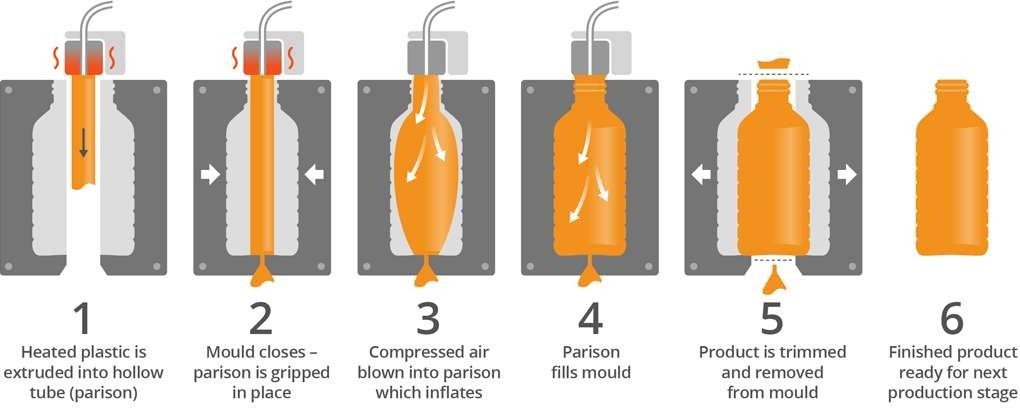
In extrusion blow moulding, a hot tube of plastic material is dropped from an extruder and captured in a water-cooled mould. Once the mould is closed, air is injected through the top of the container.
When the hot plastic blows up and the mould material freezes, it is able to maintain its shape
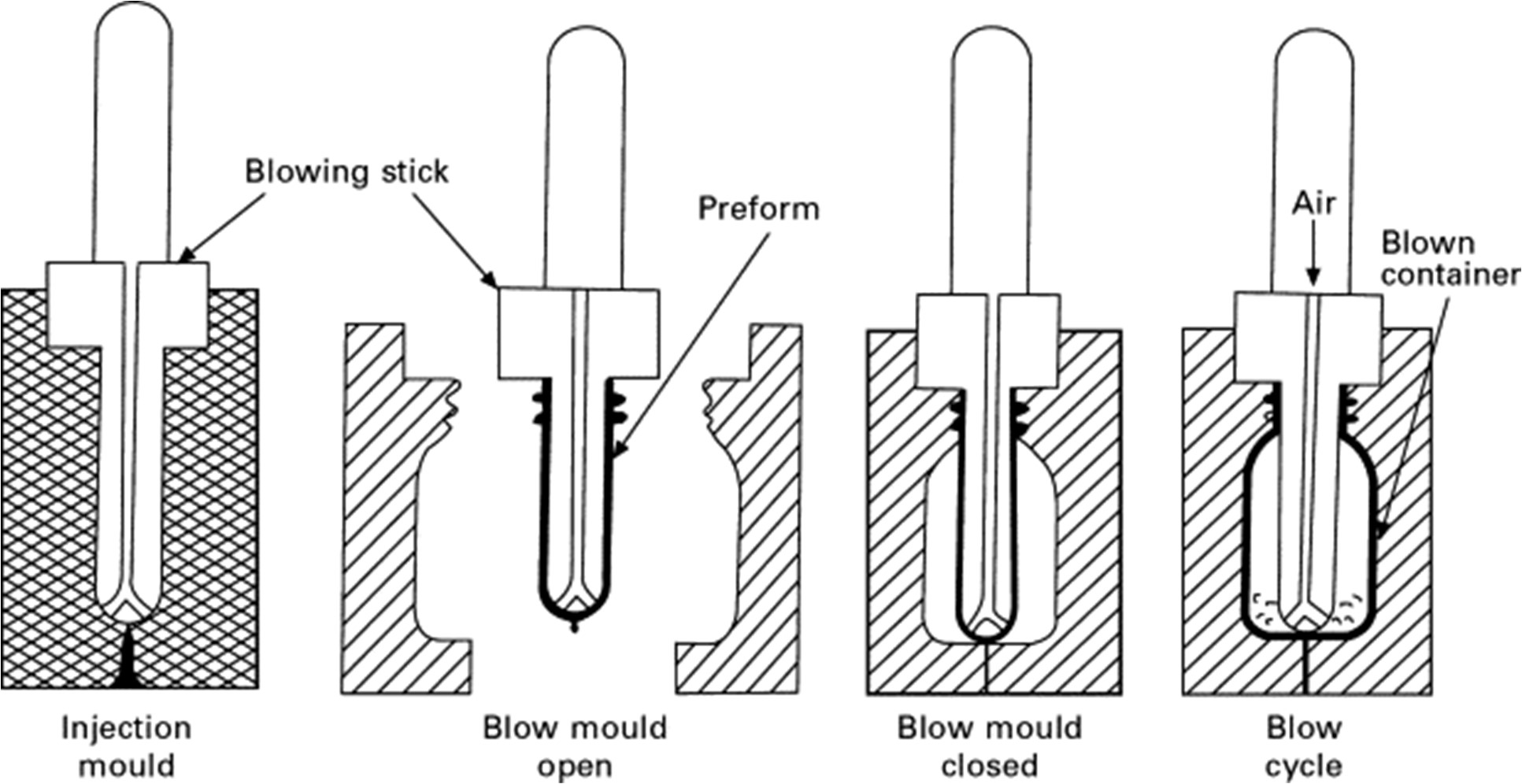
Injection Blow Moulding
In this method, hot plastic material is injected into the part of the mould that creates the neck. The injected material is then taken to the next station on the machine where it is blown up into the finished container like in the extrusion blow moudling process.
