PLC AND SCADA 4TH MODULE
Classification of I/O Modules
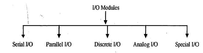
Discrete I/O modules handle two state (0 or 1) digital signals, whereas analog I/O modules deal with continuously variable analog systems. While the first type conveys either switching (ON or OFF) information of a system or a specific condition of a system, the second type indicates continuously changing signals of flow, pressure, temperature etc. The special I/O modules accept specific variable input signals like RTD, thermocouple etc.
I/O System Overview
A block schematic of an I/O system of a PLC is shown in fig. In the system there is a rack in which slots are provided to house the control processor module, power supply module and I/O modules, which are interconnected with one or more programming device. These are connected to the input and output devices through a universal I/O system.
The modules in the slots of the rack are generally draw out type, which are provided with a self-locking mechanism when in position. At the top of a module, status indication lamps and input/output marks are given

The I/O system is the section of a PLC to which all the field devices are connected
Practical I/O System and its Mapping
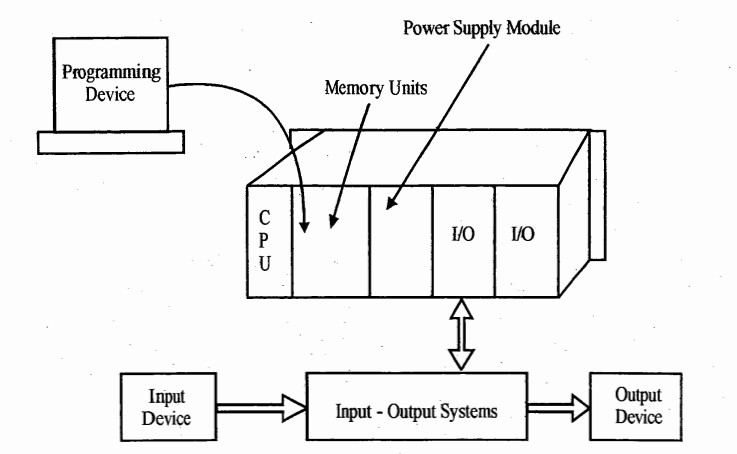
The I/O system is that section of a PLC to which all the field devices are connected. I/O modules work as an interface between the processor and the I/O devices attached to the PLC. The interface at the input modules supports, accepts and converts the incoming signals that are used by the processor.
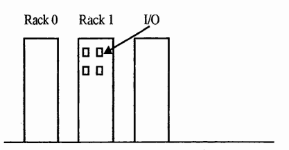
Simultaneously the interface at the output module converts signals used by the processors into signals used by the actual real world devices. As it is shown in fig above (I/O System overview). An I/O system has rack or a chassis. A rack or chassis is an enclosure with slots into which I/O modules are installed. In some small PLC, the processor, memory, rack and I/O modules are pre-packaged as one unit. Fig below shows the arrangement of the rack and module of an I/O system.
The processor of the PLC does not operate directly on I/O. Rather, it works with an image of the I/O stored in the I/O image memory. The input image table or input status file reflects the status of the input terminals. The output image table or output status file reflects the status of the output terminals.
A standard input module has 16 input points. Each input terminal corresponds to one 16 bit word of memory.

The input image table is a group of words in memory that are organized to store input data. Each I/O word or module in a chassis is mapped or assigned a specific word in the input image table. Fig shows a slot/rack 0 in which module/word 0.. module/ word-n are there each having sixteen terminals. Input and output image tables are shown on the right side of the figure. Each input/ output word having 16-terminals, is mapped in the image table as 16 bits and the CPU scams the image tables to understand the status of the input/output modules.
During program execution, inputs and outputs are only scanned once in a run loop.
Addressing Local and Expansion I/O
The local I/O provided by the CPU provides a fixed set of I/O addresses. For a chain of the expansion module, the address of the points of the modules are determined by the type of I/O and the position of the module in the chain, with respect to the preceding input or output module of the same type.
For example – an output module does not affect the addresses of the points of an input module and vice versa. Likewise, analog modules do not affect the addressing of digital modules.
Digital expansion modules always reserve I/O status files in increments of eight bit. If a module does not provide a physical point for each bit of each reserved byte, these unused bits cannot be assigned to subsequent modules in the I/OI chain. For input modules, the unused bits in reserved bytes are set to zero with each input update cycle.
Analog expansion modules are always allocated in words (16 bits). If a module does not provide physical I/O for each of these words, these I/O words are lost and are not available for assignment to subsequent modules in the I/O chain.
Input-Output Systems
Direct I/O
As the name implies, this method uses brute-force for getting the I/O and from the PLC’s processor. There is one input signal and one output signal corresponding to the number of inputs and outputs the processor supports.
This approach is typically used in very small PLCs that have all the I/O circuits in the same package as the processor. Cost is the principal advantage of internal I/O. Some flexibility, however is lost because the processor must be changed in order to change the I/O.
Direct I/O systems are most cost-effective when the number of I/O points is low (fewer than 64 I/O points). When the number of I/O points is larger, bus-oriented systems offer a better cost-performance ratio.
Parallel I/O systems
In a parallel system, a parallel I/O bus originates from the processor’s I/O interface, and individual I/O modules are plugged into this bus. The I/O module contains the necessary circuitry to decode the bus signals and convert these signals into voltage levels that can drive the necessary field loads. Each module will typically have a number of input or output points on it.
This multiplicity of I/O points is called the modularity of the I/O system. Most commercially available I/O systems have modularity's of 4,8,16 or 32. Adding more I/O points on a module will reduce the cost per I/O point and reduce the amount of space required to install a given number of I/O points. Also the greater the number of output points per module, the smaller are the loads that can be driven.
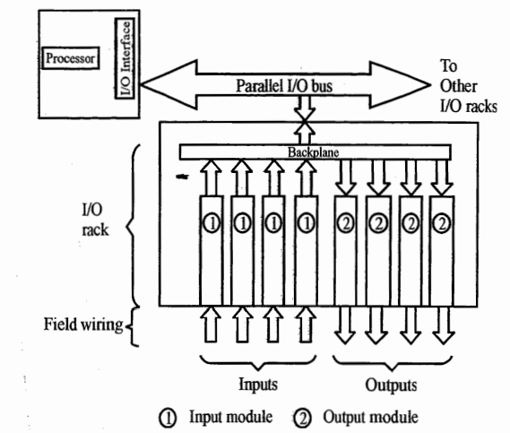
The parallel I/O system halts operation under the following conditions:
(a) The control processor enters a STOP mode
(b) When any I/O rack power supply detects the fact that the AC supply has fallen below a specific value.
(c) When the processor rack power supply detects a low AC line voltage, a power fail signal is sent to the I/O system and the control processor which halts the operation in all I/O modules
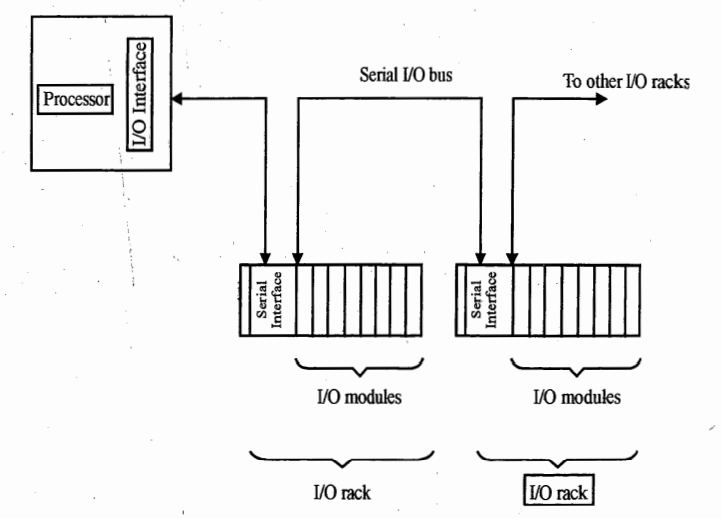
Serial I/O Systems
In parallel systems, the distance over which one can extend the I/O is limited , typically to less than 15m. If the machine is 30m long, one would have to use two PLCs. Serial I/O systems solve this problem by transmitting the I/O information over a serial data link capable of being extended over longer distances.
A serial bus originates from the processor and typically contains fewer wires than does the wiring to the loads. Large savings in wiring costs can be realised by using seral systems. A serial I/O system is shown in fig. Some of the more recent PLC models use a total serial system where each I/O module connects directly to the serial link. This can result in even more significant reductions in wiring costs.
Sinking and Sourcing
Why are they Required?
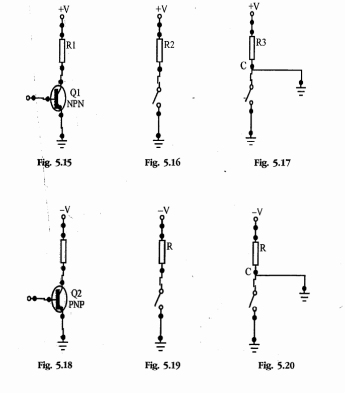
The basic reason for using sourcing and sinking lies in the fact that nowadays most of the switching and field devices are solid state devices. In solid state devices, the direction of flow of current plays an important role. Let us consider a load connected to a DC source through an NPN transistor switch as shown in fig 5.15
The equivalent circuit of figure 5.15 is shown in fig 5.16, which shows that the load is sourcing and the switch is sinking. Now consider that an earth fault has taken place at point C after the load as shown in fig 5.17. There is every possibility that the load may start, or be turned on unintentionally
The case for a PNP transistor switch is similar, as shown in fig 5.18, 5.19, 5.20. Here the switch is sourcing and the load is sinking. For any earth fault at C, the probability of mal-operation of the load is comparatively less
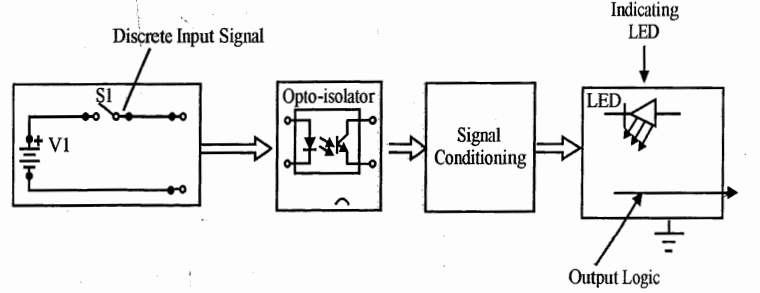
Discrete Input Module
The discrete input module is the most common input interface used with PLCs Discrete input signals from field devices can be either AC or DC
Discrete DC Input Module
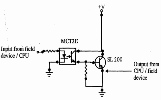
A schematic diagram of a discrete dc input module is shown in fig. A discrete input signal is received by the module from field devices isolated optically from the CPU circuit. A common opto-isolator circuit is shown in fig. The signal is conditioned and sent to the processor section and simultaneously to indicating LEDs
Discrete AC Input Module
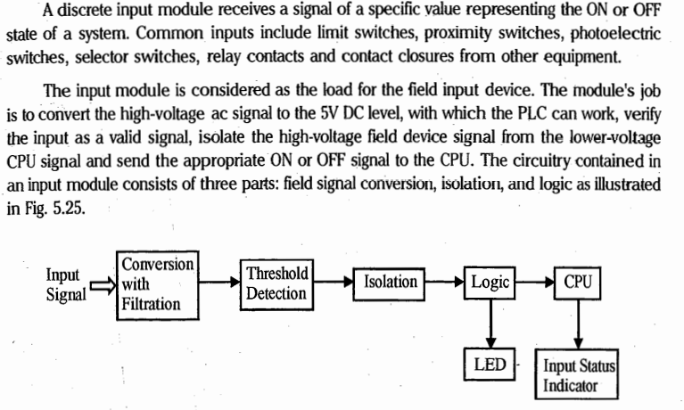
Rectifier with Filter
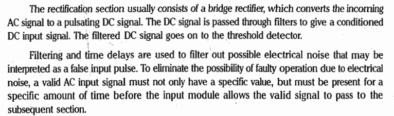
Threshold Detection
Threshold detection circuitry detects whether the level of the input signal has exceeded a predetermined set value. Depending on this it is classified as a valid ON or OFF signal. A typically valid OFF state is between 0 and 20 or 30V AC and a valid ON may be between 80 and 130V AC as shown in fig. These values may vary from on manufacturer to another
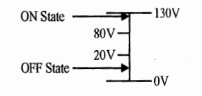
The signal area between 20 volts and 80 volts is called the undefined area. Signals falling within this undefined area may be ON or OFF, making them unstable and unreliable.
Isolation
The isolation section of the input circuit is usually made up of an optical isolator, or opto-coupler. This circuit essentially separates the high voltage signal circuit from the low voltage CPU section. A commonly used opto-isolator circuit is shown in fig. It consist of a LED and a phototransistor. Once the LED is energized, it emits light to switch on a phototransistor that is connected to the power circuit.
Optical isolation protects the low voltage CPU and its associated circuitry by preventing spikes or high voltage transients in the input circuit from transferring to the low voltage circuitry.
Special Input Modules
Special input modules fall into the category of smart modules. A smart module contains its own processor and is designed for a specific function. Some common types of special modules are discussed in subsequent sections
Resistance Temperature Detector (RTD) Input Module
A resistance temperature detector (RTD) input module interfaces a PLC to RTD temperature sensing elements and other types of resistance input devices such as potentiometers, The RTD input module converts analog input signals from a potentiometer or RTD, into input signals understood by PLC. These values are stored in PLC input table.
Thermocouple/Millivolt Input Module
The thermocouple/millivolt input module converts inputs from various thermocouple or millivolt devices into values that can be input and stored into PLC data tables. This module greatly enhances the flexibility of a PLC system by interfacing thermocouples, thus eliminating expensive thermocouple transmitters.
High Speed Encoder Input Module
When input pulses come at a faster rate, a high speed input module is used to handle them. High-speed counters are also used to interface encoders to a PLC.
Stepper Motor Control Module
A stepper motor control module is an intelligent module that is kept in a PLC chassis. It provides a digital output pulse train for microstepping stepper motor applications.
Self Diagnostic Module
In general, a PLC performs standard diagnostic tests on its system, but these tests cannot detect problems with data and control lines on an I/O bus. A self diagnostic module is capable of checking these problems. In addition, a self diagnostic module is able to check the following activities of a PLC; Processor scan-loss detection, monitoring of the I/O control signals, e.g. – input status scan control, input strobe, output strobe, system clock, power fail etc.
Communication Modules
ASCII I/O Modules and ASCII I.O modules allow the interfacing of bar code readers, meters, printers and data terminals to a PLC. ASCII modules, which accept only valid ASCII data, are not used as extensively. The RS 232 module is commonly used today.
I/O Modules in Hazardous Locations
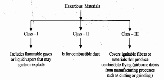
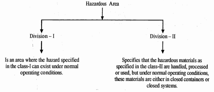
Many PLC manufacturers provide I/O modules that are rated for installation in hazardous locations. First we need to define a hazardous area. A hazardous area or environment is one that contains explosive gases or dust. These hazardous materials may be present under normal operating conditions on only in the event of equipment breakdown or an accident. The types of materials and the circumstances of their presence determine how the area is classified.
Hazardous materials are divided into three classes
Finally Hazardous materials are classified by groups.
Power Supply Requirements
A power supply is the life-line of all types of equipment and systems, therefore, it is also required by a PLC for smooth and reliable operation. For the reliable operation of a PLC system, a power supply should have the following characteristics: (i) A common AC source (ii) isolation from the power circuit (iii) emergency stops (iv)safety control systems (v) protection against line voltage variation
(i) Common AC Source
The system power supply and I/O devices should have a common AC source. If the AC source to power supply and CPU is different that to the I/O devices, it may so happen that a faulty input signal may come to the power supply when I/O section may hold healthy. This minimizes line interference. By keeping both the power supply and the I/O devices on the same power source, the user can take full advantage of the power supply’s line monitoring feature.
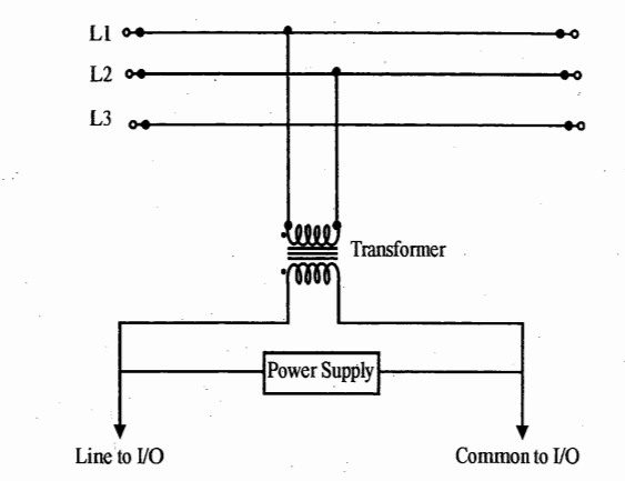
(ii) Isolation from the power circuit
To isolate the PLC circuit from the power circuit, the practice is to use an isolation transformer on the AC power line going to the controller. An isolation transformer is especially desirable when heavy equipment is likely to introduce noise into the AC line. . An isolation transformer can also serve as a step-down transformer to reduce the incoming line voltage to a desired level. The transformer should have a sufficient power rating to supply the load
(iii) Emergency Stops
The PLC system should contain a sufficient number of emergency circuits to either partially or totally stops the operation of the controller or the controlled machine or process. These circuits should be routed outside the controller, so that the user can rapidly shut down the system manually in the event of total controller failure.
Filters
Simple Capacitive Filter
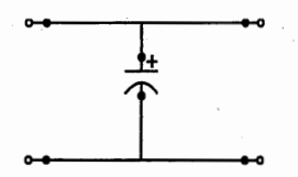
A filter circuit reduces ripple voltage to a level that can be used by the circuits using power from that particular supply. Use of power supply filters increases the average DC output and decreases the AC (ripple) component present in the output. The pulsating DC output of any rectifier contains two components; an AC component and a DC component. The rectifier is used to convert AC into PDC. For the PDC to be converted to pure DC we must reduce the AC component to the minimum possible. This is done by use of a filter circuit.
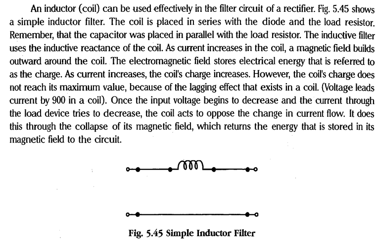
Simple Inductive Filter
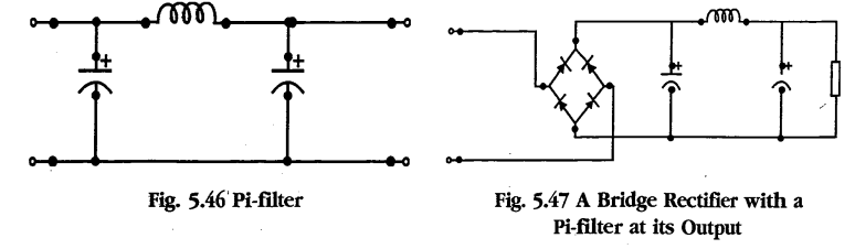
Pi-type Filter
Pi-type filters receive their name from the fact that their circuit diagrams resemble the Greek letter Pi. With the LC pi-type filter, it is possible to obtain high output voltages with good control over voltage and current variations. In the LC type, the coil opposes any change in current. This tends to stabilize both current flow through, and the voltage drop across, the load device. With the RC type, the stabilization provided by the coil is not present. Without the coil’s opposition to changes in current, voltage and current variations.
Fig shows a pi-type filter connected at the output of a bridge rectifier to get stabilized and conditioned power