
Rapid Prototyping 2nd Module
Fusion Deposition Modelling:
Fused Deposition Modelling process is an extrusion based rapid prototyping process although it works on the same layer-by-layer principle of other RP Systems –
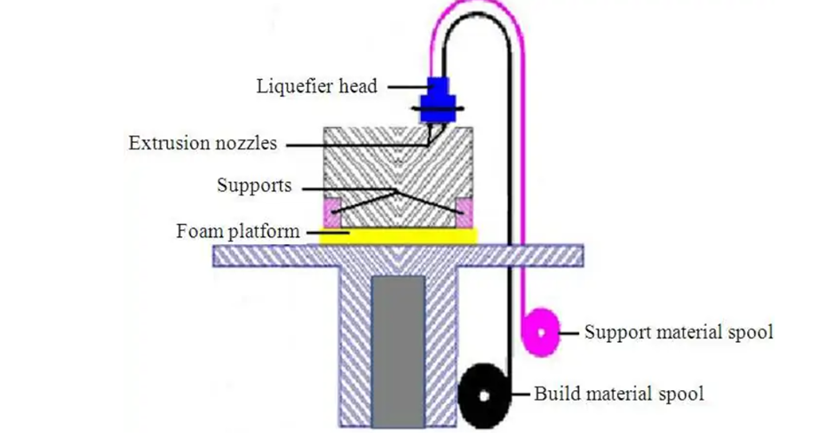
An FDM printer consists of two spools: one for the build material and another for support material. The FDM 3D printing process follows these main steps
- Step 1 – After the CAD data is input, the already loaded solid build material filament is liquified with the help of heat in the liquefier head
- Step 2 – This molten liquid plastic is fed onto the foam build platform as a layer through the extrusion nozzle that moves in all directions as defined in the CAD data. This process of adding the liquid/semi-solid layers one above the other is repeated. If the design consists of over-hangs or structures that might potentially warp or bend, support structures are used. The support material can be the same as the build material or any other material according to the choice.
- Step 3 – In case support structures were used, they are later removed once the build is complete.
Process parameter
Build Parameters:
A. Sets
Quick Slice uses sets or packages of build parameters. Sets contain all of the build instructions for a selected set of curves in a part. Sets allow a part to be built with several different settings
E.g. One set may be used for supporting structure of the part, one for part face, another for thicker sections of the part and still another for exposed surfaces of the part. This allows flexibility of building bulkier sections and internal fills quickly by getting finer details on visible areas of a part.
Sets also allow chosen sections of a part to build hollow, cross hatched or solid if so desired.
Two of the build parameters commonly worked with are road width and fill spacing.
B. Road Widths
Road Width is the width of the ribbon of molten material that is extruded from the tip.
When FDM builds a layer, it usually begins by outlining the cross section with a perimeter road, sometimes followed by one or more concentric contours inside of perimeters.
Next it begins to fill remaining internal area in a raster or hatched pattern until a complete solid layer is finished.
Therefore three types of roads are Perimeter, Contour and Raster.
C. Fill Spacing:
Fill spacing is the distance left between raster's or contours that make up interior solids of the parts. A fill spacing set at zero means that part will be built solid.
D. Creating and Outputting Roads,
Once all parameters have been set, road are created graphically by Quick Slice. The user is then allowed to preview cach slice if so desired to see if the part is going to build as required.
E. Getting a Build Time Estimate:
Quick slice has a very good build time estimator which activates when an SML file is written. SML stands for Stratasys Machine Language.
Basically it displays in the command windows, the approximate amount of time and material to be used for given part. Build time estimate allows for a efficient tracking and scheduling of FDM system work loads.
F. Building a part:
The FDM receives a SML file and will begin by moving the head to the extreme X and Y portions to find it and then raises the platen to a point
The FDM receives a SML file and will begin by moving the head to the extreme X and Y portions to find it and then raises the platen to a point to where the foam substrate is just below heated tips. After checking the raw material supply and temperature settings, the user then manually places the head at point where the part has to be built on the foam and then presses a button to begin building. After that FDM will build part completely without any user intervention.
G. Finishing a FDM parts
FDM parts are an easiest part to finish.
Applications:
a. Concept or Design Visualization.
b. Direct Use Components.
c. Investment Casting.
d. Medical Applications
e. Flexible Components.
f. Conceptual modeling.
g. Fit, form and functional applications and models for further manufacturing procedures.
h. Investment casting and injection molding.
Advantages
a. Strength and temperature capability of build materials.
b. Safe laser free operation.
c. Easy Post Processing.
d. Quick and cheap generation of models.
e. Easy and convenient date building.
f. No worry of possible exposure to toxic chemicals, lasers, or a liquid polymer bath.
g. No wastage of material during or after producing the model.
h. No requirement of clean-up.
i. Quick change of materials.
Disadvantages:
a. Process is slower than laser based systems.
b. Build Speed is low.
c. Thin vertical column prove difficult to build with FDM
d. Physical contact with extrusion can sometimes topple or at least shift thin vertical columns and walls.
e. Restricted accuracy due to the shape of the material used: wire of 1.27 mm diameter.
SOLID GROUND CURING
The early versions of the system weighed several tons and required a sealed room. Size was made more manageable and the system sealed to prevent exposure to photopolymers, but it was still very large.Instead of using a laser to expose and harden photopolymer element by element within a layer as is done in stereo lithography, SGC uses a mask to expose the entire object layer at once with a burst of intense UV light. The method of generating the masks is based on electrophotography (xerography).
Highlights
1. Large parts of 500×500×350mm can be fabricated quickly.
2.High speed allows production of many parts.
3.Masks are created.
4.No post curing required
5. Milling step ensures flatness of subsequent layers.
6.Wax supports model, hence no extra support is required.
7.Create a lot of wastes.
8. Not as prevalent as SLA and SLS but gaining ground because of high throughput and large parts.
Principle of operation-
First a CAD model of the part is created and it is sliced in to layers using cubitos data front end software.
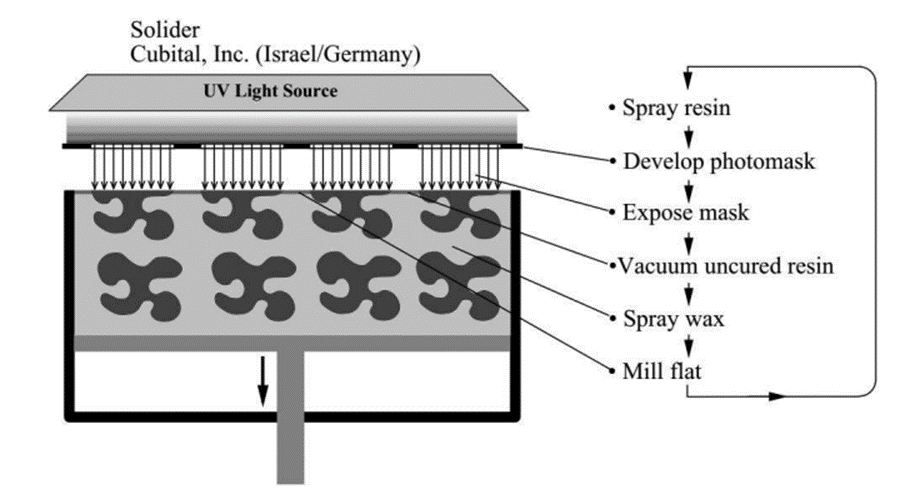
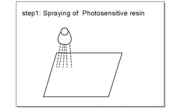
1. Spray photosensitive resin: At the beginning of a layer creation step the flat work surface is sprayed with photosensitive resin.
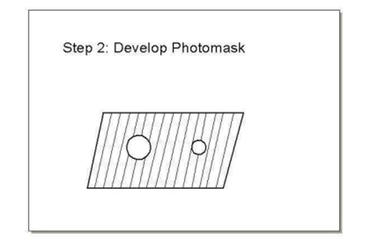
2. Development of photo mask For each layer a photo mask is produced using cubitals proprietary ionographic printing technique.
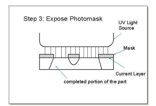
3. Expose photo mask: The photo mask is positioned over the work surface a powerful UV lamp hardens the exposed photosensitive resin.
4. Vacuum uncured retin and solidify the remnants After the layer is cured all the uncured resin is vacuumed for recycling leaving the hardened area intact the cured layer is passed beneath a strong linear
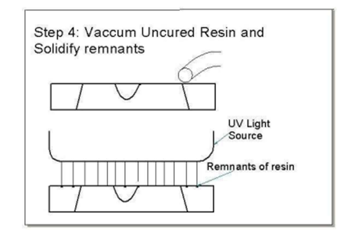
UV lamp to fullycure in and solidify any remnants particles as shown in figure.
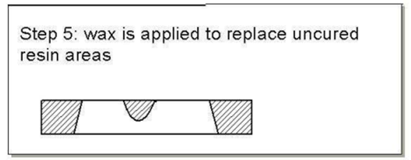
5. Wax is applied to replace uncured resin area: Waxreplaces the cavities left by vacuuming the liquid resin. The wax is hardened by cooling to provide continuous solid support for the model as it is fabricated extra supports are not needed.
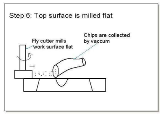
6. The top surface is milled flat: In the final step before the next layer, the wax resin surface is milled flat to an accurate reliable finish for next layer.
Once all layers are completed the wax is removed and any finishing operations such as sanding etc can be performed no post curing is necessary.
Advantages
· The entire layer is solidified at once.
· Reduction in the part build time for multipart builds.
· Larger prototypes can be nested to utilize the build volume fully.
· No post curing is required.
Disadvantages
· The system is large, noisy and heavy.
· It wastes a large amount of wax which cannot be recycled.
· SGC systems are prone to breakdowns.
· The resin models of SGC are not suitable for investment casting because coefficient of thermal expansion is more than ceramics in resin which may lead to cracks in casting.
Appliations
it is a rarely used method. There are some new variations, but they don’t differ from LED printing, applying digital projectors.
Machine details
Solid Ground Curing Machine Details
Cubital Machine : The highlighted features of cubital machine over the FDM or Stereolithography are fastest making of models with huge volume of production at the same time. The main process in making of model is successive layers of liquid photo polymer resins which are cured using the UV light
Constructional Details :
The cubital machine contains the following parts :
Polymer spreader:
This infects the liquid polymer resin with the help of high compressed air .
Electrical charging : This is linked with software which manipulates the object boundary at each and every layer .
Mask developer: It is a device which gives the block like coating on the plate on which the plate covers with the coating except from the profile boundary.
Mask erasure: It is used to erase the mask from the plate when the process iteration is over
Wax platform: This is a table-like structure on which the polymer layer to be deposited.
Residual Polymer cleaner: This is a sort of arrangement to suck the wasted polymer from the table after the layer boundary is solidified with the help of UV light.
Wax spreader : This pours the wax where ever required on the table up to the depth of the layer polymer.
Wax cooling plate: This cools the entire object layer along with the wax .
Milling head: This is a cutter which cuts the portion upon the layer to finish the layer surface to pour the polymer in the second run .
UV light arrangement: It is an arrangement which we use to solidify the layer.
Laminated Object Manufacturing:
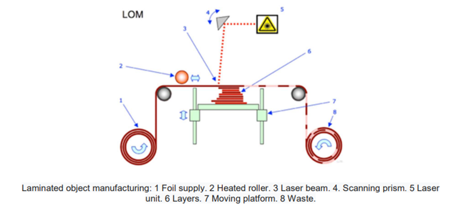
·Materals is usually a paper sheet laminated with adhesive on on side but plastic and and material laminates are appearing
·Layer fabrication starts with sheet being adhered to substrate with the heated roller · The laser then traces out the outline of the layer
· Non part areas are cross-hatched to facilitate removal of waste material
· Once the laser cutting is done, the platform moves down and out of the way so that fresh sheet material can be rolled into position
· Once new material is in position the platform moves back p to one layer below its previous position
· The process is repeated until the finishing of last layer
· All excess material is removed afterwards ·Mechanical post processing can feature grinding drilling etc
Advantages:
· Ability to produce large scaled models
· Uses very inexpensive paper
· Fast and accurate
· Good handling strength
· Environmentally friendly
· Not health threatening
· Precision claimed to be in around (+ or - 0.05 in)
· Variety of material can be used such as paper, plastics, composites and ceramics
Disadvantages:
· Paper is cheap but is not very stable
· Need decubing which requires a lot of labour
· Produce smoke or fumes
· Fire hazard
· Not ideal for making complex geometries
· It is not used to create functional prototypes
Application:
For creating scaled models
Conceptual Prototypes that can be tested for form or design
It can be used to make patterns for use in traditional manufacturing such as sand molded casting investment casting etc
LOM materials
This technology is very versatile as almost any material can be glued. During this additive manufacturing process, layers of adhesive-coated paper, plastic, or metal laminates are successively glued together. The more common material used is paper as it is easily cut. Plastic can also be used, using a blade or a laser during the cutting stage. Metallic sheets are more unusual because the cutting stage is more complicated.
Process Parameters
There are various controlling parameters such as laser power, heater speed, material advance margin, and support wall thickness and heater compression.
Laser Power: It is the percentage of total laser output wattage.
For e.g. LOM 1015 is operated at a laser power of about 9% of maximum 25W laser or approximately 2.25W. This value will be different for various materials or machines but essentially it is set to cut through only one sheet of build material.
Heater Speed: It is the rate at which hot roller passes across the top of the part. The rate is given in inches/second. It is usually 6"/sec for "initial pass and 3"/sec for returning pass of heater. The heater speed effects the lamination of the sheet so it must be set low enough to get a good bond between layers.
Material Advance Margins: It is the distance the paper is advanced in addition to length of the part.
Support Wall Thickness: It controls the outer support box walls throughout a part. The support wall thickness is generally set 0.25" in the X and Y direction, although this value can be changed by operator.
Compression: It is used to set the pressure that the heater roller exerts on the layer. It is measured in inches which are basically the distance the roller is lifted from its initial track by the top surface of part. Values for compression will vary for different machines and materials, but are typically 0.015"-0.025".

