
Rapid Prototyping 3rd Module
SELECTIVE LASER SINTERING
Type of machine
Selective Laser Sintering is a rapid prototyping process that builds models from a wide variety of materials using an additive fabrication method.
Selective Laser Sintering was developed by university of Texas Austin in 1987.The build media for Selective Laser Sintering comes in powder form which is fused together by a powerful carbon dioxide laser to form the final product.
DTM sinter station 2500 is the machine used for the process. Selective Laser Sintering begins like most other rapid prototyping processes with a standard .STL CAD file format.DTM view software uses the .STL files.
This software do the required orientation and scaling of parts. This machine has auto nesting capabilities which will place multiple part optimally in the build chamber for best processing speed and results.
Once the .STL file is placed and parameters are set the model is directly built from the file
All SLS printers work based on the previously highlighted procedures. However, there are differences based on their laser type, build volume, and 3D design. There are many types of SLS printers in the market. However, they are majorly divided into two categories, namely:
· Traditional Selective Laser Sintering 3D Printers
Traditional SLS 3D printers are the right printers for service bureaus and large enterprises due to their high price and high build volume. They use single or multiple high-power lasers for sintering and require an inert environment to prevent oxidation and degradation of the powdered material.
Traditional SLS 3D printers take a large amount of space, with the smallest one taking up about 10m² space. They also have a high cost, with starting price being around $100,000. Consequently, they are not accessible by many businesses.
· Benchtop Industrial Selective Laser Sintering Printers
Benchtop industrial SLS printers are unlike traditional ones as there is a trade-off in their capability. Trade-offs can be lower part quality and complex, manual workflows, which will affect their use in industrial and production settings. They have a small size compared to traditional printers but with a smaller build volume. Nevertheless, they produce high-quality parts.
Principle of Operation:
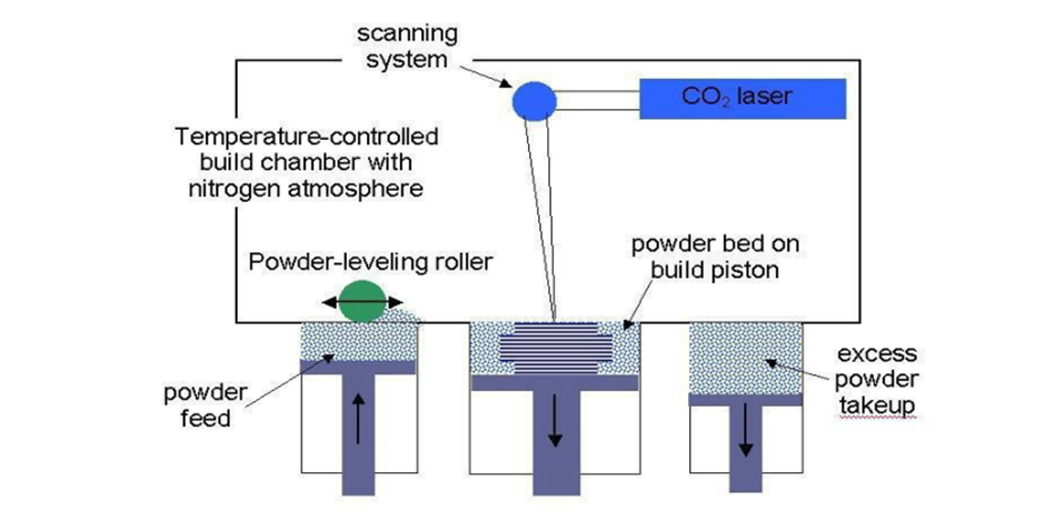
The Selective Laser Sintering process involves tiny particles of polymer powders material being fused together via heat from a high power laser. A thermal source is used to fuse the powder particles together at a specific location on the build platform to develop a solid, 3D printed part.
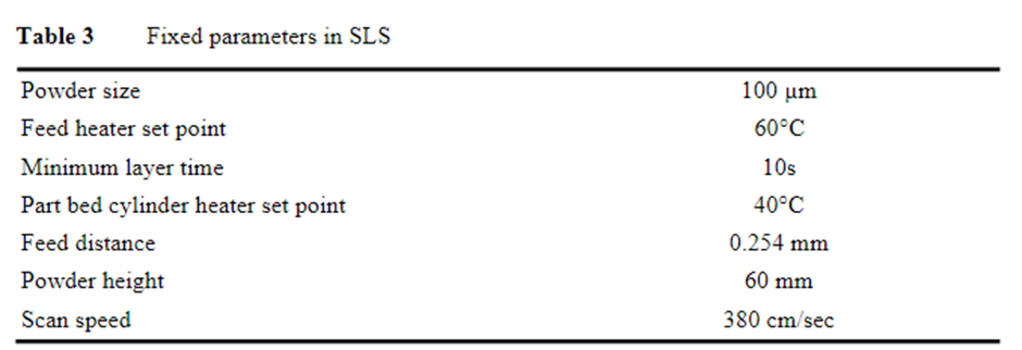
Before printing, the powder is heated to a temperature just below the material’s melting point. The recoating blade then deposits one layer height’s powder on the build platform. SLS often uses 0.1mm / 100 micron layer heights.
The CO2 laser then selectively sinters the powder according to the dimensions of the part — solidifying it. It will trace the whole layer, before moving down to the next layer and starting again. This continues repeatedly, layer by layer, until the finished part is done.
This process is like SLA in that a laser is focused on a specific point, and the platform moves after each layer has been finished. It is also like fused deposition modeling in that parts are completed layer-by-layer through the melting of a material, though FDM uses plastic filaments instead of powder.
Unlike SLA or FDM, selective laser sintering doesn’t require any supports, as the powder in the bin encompasses the part and keeps it stable, no matter the geometry. This is a major advantage as printing supports can affect surface finish, print speed, and means more intricate designs can be printed.
SLS is also one of the 3D printing technologies best suited for batch production.
Purpose of Selective Laser Sintering:
To provide a prototyping tool
To decrease the time and cost of design to product cycle.
It can use wide variety of materials to accommodate multiple application throughout the manufacturing process
Applications:
1. As conceptual models.
2.Functional prototypes.
3.As Pattern masters.
4. prosthetics and orthotics (i.e., limb replacements + braces) and surgical models and tools
5. In Aersoppace industry it is used to make aircraft interior parts and cabin components such as video monitoring shrouds and air vent grills
6. Can be used to make products for Consumer Industries i.e Chanel uses SLS to make mascara brushes and Adidas use the technology for producing customized insoles and sandals.
7. Wide Tunnel Test Models
8.Design Evaluation models (Form fit and Function)
Advantages: 1. Wide range of build materials.
2.High throughput capabilities.
3.Self-supporting build envelop.
4.Parts are completed faster.
5.Damage is less.
6.Less wastage of material
Disadvantages:
1. Initial cost of system is high.
2.High operational and maintenance cost.
3.Peripheral and facility requirement.
4. Limitation In Raw-Material
5. Difficult Post Processing
process parameters,
1. Part bed Temperature
· The part bed is the central region of the SLS machine (DTM Sinter station 200) where the part is built
· The part bed temperature is controlled primarily by the heater underneath the build area
· The temperature should be lower than meting temperature of the powder
· The higher the temperature is set, the less the incident energy is required during the SLS process
2. Layer thickeness
· Layer thickness is a measure of the thickeness of each layer during the SLS process
· It is also the depth by which the part piston is lowered after the laser scanning of each layer
· A thicker layer requires greater incident energy
· Thicker layers will not give us very good surface finish because of ‘stair stepping’
3. Laser power
· The longer the laser dwells in a particular location, the deeper the fusion depth and the larger the melt pool diameter.
· Typical layer thickness range from 0.1 to 0.15mm
4.Laser scan speed around 380cm/sec
5. Energy density
· Energy density is defined as the amount of energy input per unit area
· It is dependent upon laser power scan speed and scan spacing and is determined by the following equation ED = LP/(BSxSS)
Where ED is the energy density,
Lp is the laser power
BS is the beam scan speed and SS is the scan spacing.
· The laser power scan speed and scan spacing need to be optimised according to the amou t of input energy required to fuse the particles in the layer
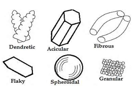
6.Powder shape
Data preparation for SLS
· The SLS technology is housed in the sinterstaion line of systems by DTM
· The SLS process begins like most other RP processes with the standard .STL CAD file format which is exported now by most 3D CAD packages
· The DTMView software can import one or several .STL files and allow you to orient or scale the parts as you see necessary
· The 2500 systems have autonesting capabilities which will place multiple parts optimally in the build chamber for the best processing speed and results
· Once the .STL files are placed and processing parameters are set, the models are built directly from the file
· With the build piston at the top, a thin layer of powder is spread across the build area by a roller/sweeper from one of the feed pistons
· The laser then cures in a raster sweep motion the cross sectional area of the parts being built
Materials of Selective Laser Sintering
SLS materials are always powdered form, and they include plastic polymers, ceramic, and glass. Of the many materials, polyamides/nylons are the most common due to their ideal sintering behavior and mechanical properties (e.g., durability, environmental stability, and impact resistance). Many variants are used in SLS printing, each suitable for different industries. Below are variants you can apply to your project.
· Nylon 11
· Nylon 12
· Nylon 12 GF
· Aluminium-Filled Nylon
· Carbon-Fiber Filled Nylon (PA-FR)
Post-processing Options of SLS Printing
After printing, you can directly use the SLS 3D printed parts. However, you can also subject the printed parts to other post-processing options for better aesthetics or functionality. Common post-processing options include:
· Bead Blasting
· Polishing
· Electroplating
· Dyeing
· Painting
3-D printers:
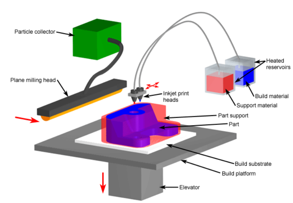
Binder printing methods were developed in the early 1990s, primarily at MIT. They developed the 3D printing (3DP) process in which a binder is printed onto a powder bed to form part cross sections. Contrast this concept with SLS, where a laser melts powder particles to define a part cross section.
A recoating system similar to SLS machines then deposits another layer of powder, enabling the machine to print binder to define the next cross section. Three-dimensional printing, or 3DP, is an MIT-licensed process, whereby liquid binder is jetted onto a powder media using ink jets to "print" a physical part from computer aided design (CAD) data.
Z Corporation (Z Corp) incorporates the 3DP process into the Z402 system. The relatively inexpensive Z402 is directed toward building concept-verification models primarily, as the dimensional accuracy and surface roughness of the parts are less than higher end systems.
The initial powder used was starch based and the binder was water based, however now the most commonly used powder is a new gypsum based material with a new binder system as well. Models are built up from bottom to top with layers of the starch powder and binder printed in the shape of the cross sections of the part.
The resulting porous model is then infiltrated with wax or another hardener to give the part dexterity. The Z402 is the fastest modeller on the market, with speeds 5 to 10 times faster than other current rapid prototyping (RP) systems. A wide range of polymer, metal, and ceramic materials have been processed in this manner.
Thermal Ink jet Printer Ink jet printing comes from the printer and plotter industry where the technique involves shooting tiny droplets of ink on paper to produce graphic images. RP ink jet techniques utilize ink jet technology to shoot droplets of liquid-to-solid compound and form a layer of an RP model.
The additive fabrication technique of inkjet printing is based on the 2D printer technique of using a jet to deposit tiny drops of ink onto paper. In the additive process, the ink is replaced with thermoplastic and wax materials, which are held in a melted state.
When printed, liquid drops of these materials instantly cool and solidify to form a layer of the part. For this reason, the process if often referred to as thermal phase change inkjet printing. Inkjet printing offers the advantages of excellent accuracy and surface finishes. However, the limitations include slow build speeds, few material options, and fragile parts. As a result, the most common application of inkjet printing is prototypes used for form and fit testing. Other applications include jewellery, medical devices, and high-precisions products.
Several manufactures have developed different inkjet printing devices that use the basic technique described above.
Inkjet printers from Solidscape Inc., such as the ModelMaker (MM), use a single jet for the build material and another jet for support material.
3D Systems has implemented their MultiJet Moldeling (MJM) technology into their ThermoJet Modeler machines that utilize several hundred nozzles to enable faster build times
Common ink jet printing techniques, such as
a) Sanders Model Maker.
b) Multi-Jet Modelling.
c) Z402 Ink Jet System.
d) Three-Dimensional Printing.
e) Genisys Xs printer.
f) Object Quadra system

