Rapid Prototyping 4th Module
Rapid Tooling
Rapid tooling refers to mold cavities that are either directly or indirectly fabricated using rapid prototyping (RP) techniques.
Rapid tooling is divided into two types: (i) Direct tooling, (ii) Indirect tooling- secondary process.
· In direct method, the fabricated part by RP machine itself is used as tool.
· In indirect method the part fabricated by RP machine is used as pattern in a secondary process.
· The resulting part from the secondary process is used as the tool
Indirect Rapid Tooling:
As Additive manufacturing is becoming more mature, material properties, accuracy, cost and lead time are improving to permitting to be employed for production of tools.
Indirect RT methods are called indirect because they use Additive manufacturing pattern obtained by appropriate AM technique as a model for mould and die making.
Pattern is created by Additive manufacturing and the pattern is used to fabricate the tool Examples: Patterns for sand casting and investment casting Electrodes for EDM
Indirect tooling methods are intended as prototyping or pre-production tooling processes and not production methods.
Most any rapid prototyping process can yield patterns for indirect tooling.
Silicon rubber tooling
The most widely used indirect RT methods are to use AM masters to make silicon room temperature vulcanizing moulds for plastic parts and as sacrificial models or investment casting of metal parts.
These processes are usually known as Soft Tooling Techniques. The purpose of silicone RTV tools is to create urethane or epoxy prototypes, often under vacuum (hence the term vacuum casting)
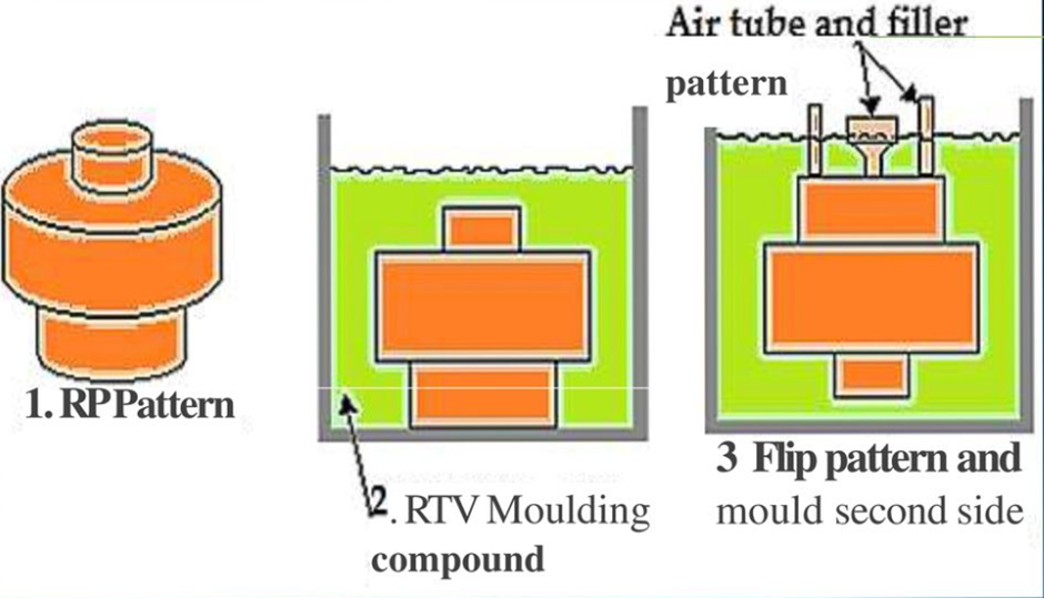
Steps-
• An RP process is used to fabricate the pattern.
• The pattern is fix turned into a holding box a coated with a special release agent (wax based aerosol or petroleum jelly mixture) to prevent it from sticking to the silicon rubber mould.
• The Silicon rubber is then blended, vacuumed to remove air bubbles & pour into the box around the pattern until the pattern is completely encapsulated.
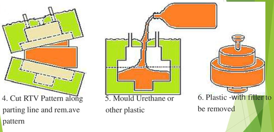
• After the rubber is fully cured (12-24 hours curing time), the box is removed & the mould is cut into two halves along a predetermined parting line.
• At this point the original pattern is cooled from the silicon rubber which can be placed back together & repeatedly filled with hot wax & plastic to fabricate multiple patterns.
• These tools are generally not injected due to soft nature of material so the final part material must be poured into the mould cavity per each cycle
Aluminium filled epoxy tooling
Epoxy tools are used to manufacture prototype parts or limited runs of production parts. The mould life normally is up to 200 pieces.This process is similar to that of vacuum casting.
The only difference being that instead if silicone rubber, the material used is aluminium filled epoxy. Once the mould is made from this material, it can be put on a moulding machine and components can be moulded in actual material of choice.
Steps-
· The fabrication of moulds begins with the construction of a simple frame around the parting line of Additive manufacturing model.
· Sprue, gates and runners can be added or cut later on once the mould is finished. The exposed surface of the model is coated with a release agent and epoxy is poured over the model.
· Aluminum powder is usually added to epoxy resin and copper cooling lines can also be placed at this stage to increase the thermal conductivity of the mould.
· Metal inserts are placed in areas where the epoxy is unlikely to withstand the pressures of the injection-moulding process.
· Epoxy is then cast against the pattern and parting lineblock combination to create the first side of the tool.
· Once the epoxy is cured the assembly is inverted and the parting line block is removed leaving the pattern embedded in the side of the tool just cast.
· Another frame is constructed and epoxy is poured to form the other side of the tool.
· Then the second side of the tool is cured. The two halves of the tool are separated and the pattern is removed
Epoxy tools are used as:-
Moulds for prototype injection
Plastic Moulds for casting Compression
Moulds Reaction Injection Moulds
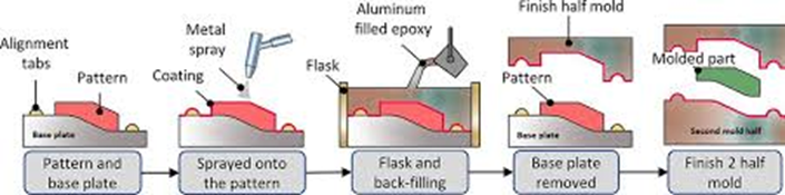
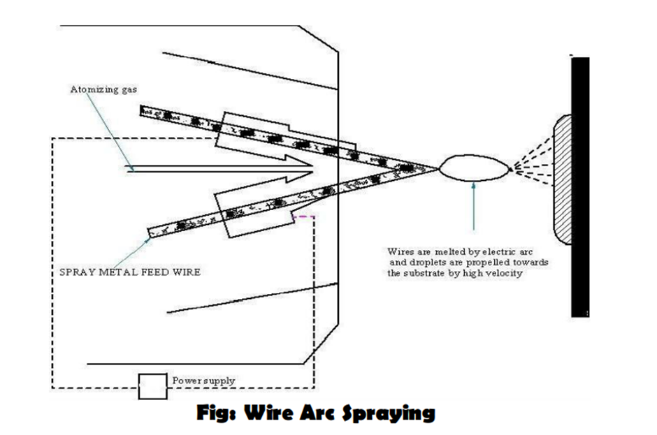
Spray metal tooling
These are the thermal metal deposition techniques such as wire arc spray and vacuum plasma deposition. These are been developed to coat low temperature substrates with metallic materials. This results in a range of low cost tools that can provide varying degrees of durability under injection pressures.
The concept is to first deploy a high temperature, high hardness shell material to an RP pattern and then backfill the remainder of the two shell with inexpensive low strength, low temperature materials on tooling channels. This provides a hard durable face that will endure the forces on temperature of injection moulding and a soft banking that can be worked for optimal thermal conductivity and heat transfer from the body.
Steps-
· In Wire Arc Spray, the metal to be deposited comes in filament form. Two filaments are fed into the device, one is positively charged and the other is negatively charged until they meet and create an electric arc.
· This arc melts the metal filaments while simultaneously a high velocity gas flows through the arc zone and propels the atomized metal particles on to the RP pattern.
· The spray pattern is either controlled manually or automatically by robotic control. Metal can be applied in successive thin coats to very low temperature of RP patterns without deformation of geometry.
· Current wire arc technologies are limited to low temperature materials, however as well as to metals available in filament form.
Vacuum Plasma Spray technologies are more suited in higher melting temperature metals. The deposition material in this case comes in powder form which is then melted, accelerated and deposited by plasma generated under vacuum.
3D keltool
The word "Keltool" refers to the proprietary powder metal sintering process, which involves infiltrating a fused metal part with copper alloy. This alloy fills in the voids in the otherwise porous material, producing a surface with the finish and hardness necessary for an injection mould
This process is based on metal sintering process. This process converts RP master patterns into production tool inserts with very good definition and surface finish. The production of inserts including the 3D Keltool process involves the following steps
· Fabricating the master patterns of core and cavity.
· Producing RTV silicon rubber mould from the pattern.
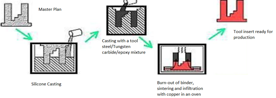
· Filling the silicon rubber mould with metal mixtures to produce green parts duplicating the masters. Metal mixture is powdered steel, tungsten carbide and polymer binder with particle sizes of around 5 mm. Green parts are powdered metal held together by polymer binder.
· Firing the green parts in a furnace to remove the plastic binder and sintering the metal particles together.
· Infiltrating the sintered parts (70% dense inserts) with copper in the second furnace cycle to fill the 30% void space.
· Finishing the core and cavity.
3D Keltool inserts can be built in two materials. Sterlite of A6 composite tool steel. The material properties allow the inserts using this process to withstand more than 10lakh mould cycles.
Direct Rapid Tooling:
Indirect methods for tool production necessitate a minimum of one intermediate replication process. This might result in a loss of accuracy and to increase the time for building the tool.
To overcome some of the drawbacks of indirect method, new rapid tooling methods have come into existence that allow injection moulding and die casting inserts to be built directly from 3D CAD model
Direct Rapid Tooling Processes can be divided into two main groups
1st group:
It includes less expensive methods with shorter lead times.
Direct RT methods that satisfy these requirements are called methods for firm tooling or bridge tooling.
AM processes for firm tooling fill the gap between soft and hard tooling.
Example - DTM COPPER PA TOOLING DTM SANDFORM TOOLING 3DP CERAMIC SHELLS
2nd group:
Solutions for hard tooling are based on fabrication of sintered metal steel, iron copper powder inserts infiltrated with copper or bronze.
It includes AM methods that allow inserts for pre production and production tools to be built.
These methods come under hard tooling.
Example - EOS DIRECT TOOLDTM RAPID TOOL PROCESSLOM TOOLING IN CERAMIC
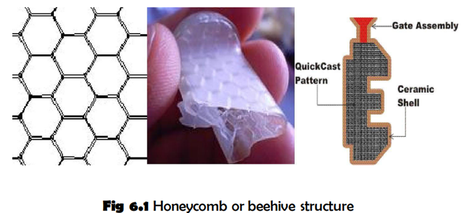
Quick cast process-
• QuickCast is a process that allows for the creation of direct shell investment castings using "QuickCast" Stereolithography (SLA) patterns.
• The QuickCast method allows you to rapidly build highly accurate resin patterns in Stereolithography, bypassing the expensive and time-consuming step of tooling.
• QuickCast facilitates rapid production of small quantities of metal parts in much less time than traditional methods.
• Instead of the SLA part being completely solid, QuickCast eliminates 95% of the internal mass of the part.
• This is achieved by curing only external surfaces and an internal lattice structure. Holes in the bottom of the part allow uncured resin to drain from the part.
• The result is a 65-80% hollow part with an internal beehive or Honeycomb type lattice structure, which gives the part tremendous structural integrity.
• Beehive or honeycomb structure avoids expansion during burning, provides high structural integrity.
QuickCast, a 3D Systems proprietary process, replaces traditional wax patterns for investment casting with stereolithography (SLA) patterns created in a robust, durable material, without tooling and without delay.
The net result is QuickCast patterns in as little as 2 to 4 days and quality metal castings in 1 to 4 weeks. The QuickCast part resembles a beehive hatch pattern and ends up being about 80% hollow. It will burn out in the investment casting process with very little residue.
PROCESS DESCRIPTION:
· A Stereolithography QuickCast pattern is created from an STL file.
· The pattern is leak tested to make sure it is air tight.
· An investment caster is chosen (based on experience & material required).
· QuickCast pattern is given to the caster.
· Caster puts part through ceramic coating process and performs firing procedure to burn out SLA pattern.
Points to be considered For QuickCast:
· They must be reliable and repeatable.
· The pattern must be sufficiently accurate to accommodate normal investment casting problem.
· The resulting casting must be metallurgically sound.
· QuickCast patterns must be fully sealed to ensure no ceramic slurry leaks into the hollow structure.
· Since humidity and temperature can have an adverse impact on QuickCast patterns, special care must be taken in shipment.
Sand casting tooling
Sand casting is often used to produce large metal parts with low requirement of surface quality.Rapid prototyping techniques can be utilized to fabricate master patterns using sand moulds.
These moulds are produced by placing rapid prototyping patterns in sand box which is then filled and packed with sand to form the mould cavity.
When employing rapid prototyping techniques it is much more convenient to build patterns which include compensation for shrinkage of the castings as well as additional machining stock for areas requiring machining after casting.
The other benefits are that it significantly reduces lead time and increase pattern accuracy.
Patterns for the sand casting can be made by direct and indirect rapid tooling.
Direct routes:
Patterns for sand casting: This included epoxy patterns in SLA system, ABS plastic patterns in FDM system, paper pattern in LOM system, PVC plastic pattern in SDP system and resin pattern in Objet system.
Indirect routes:
Patterns for sand casting: The RP patterns SLA FDM and LOM are used as master patterns to fabricate a silicone rubber mould, which is used for making multiple hard patterns from polyurethane (PU) and epoxy rubber.
Laminate tooling (LOM Tools)
LOM process produces parts using sheets of paper.
Experiments to build moulds directly or coated with thin layer of metal has been reported.
Moulds built this way can only be used for low melting thermoplastics and are not suitable for injection moulding or blow moulding of common thermoplastics.
For this reason, new materials based on epoxy or ceramic capable of withstanding harsh operating conditions have been developed.
Polymer sheets: These sheets consist of glass and ceramic fibres in a B-staged epoxy matrix. Parts made with this material require post curing at 175oc for one hour. Once fully cured they have good compressive properties and heat deflection temperature of 290 degree C
Ceramic sheets: Two ceramic materials have been developed for LOM, a sinterable AIN ceramic and a silicon infiltrable SiC ceramic. Both materials are mixed with 55% by volume of polymeric binder.The ceramic process is less advanced and requires more software and hardware modifications to the LOM Machine
To produce a mold tool, the CAD model must take the form of the required cavity. By cutting all of the slices of the cavity in sheet metal, a stack of laminates can be made to replicate the original CAD model.
Using either clamping or diffusion bonding, it is possible to create a pseudo-solid cavity in hardened tool steel without the need for complex post process cutter path planning.
Due to the use of relatively thick laminates - typically 0.040 inch (1 mm) - the surface finish of the tools is generally poor; therefore, some form of finish machining is generally required.
Laminated tools have been used successfully for a variety of techniques including press tools, blow molding, injection molding and thermal forming
.Soft Tooling:
It can be used to intake multiple wax or plastic parts using conventional injection moulding techniques. It produces short term production patterns. Injected wax patterns can be used to produce castings. Soft tools can usually be fabricated for ten times less than a machine tool.
Hard Tooling:
Patterns are fabricated by machining either tool steel or aluminum into the negative shape of the desired component. Steel tools are very expensive yet typically last indefinitely building millions of parts in a mass production environment. Aluminum tools are less expensive than steel and are used for lower production quantities.
Comparison of Soft & Hard Tooling
|
Soft
Tooling |
Hard
Tooling |
|
Low Cost Tooling |
Higher Cost Tooling |
|
Excellent For Medium-Low Volumes High Mix |
Lower Piece Part Cost |
|
Higher Piece Part Cost |
NO Design Flexibility |
|
Faster Lead Time And Response |
Repeatability |
|
More Flexibility To Change Design |
Longer Lead Time Due To Tooling Lead Time |
|
Increased Product Variance |
Process For High Volumes |
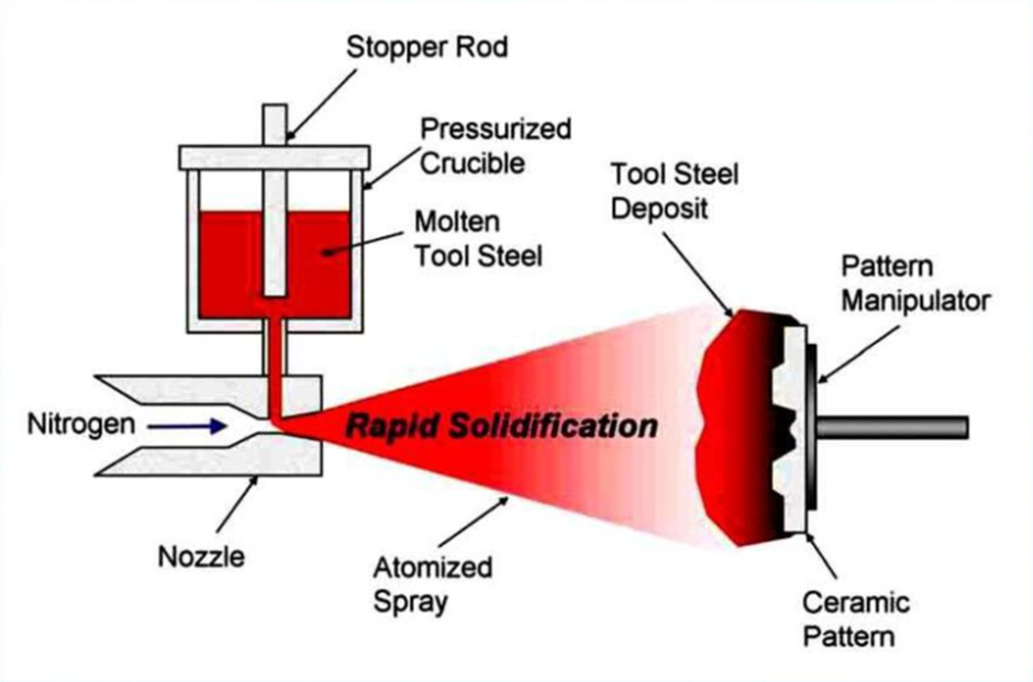
Rapid Solidfication Tooling Process-
· RSP stands for Rapid Solidification Process
· We create a plastic model using SLA
And then we make moulds with either by epoxy tooling or spray metal onto it
· But most of the cases,ceramics are used
· What’s significant in that is that we atomise the metal down to as small as 5 microns
· When the metal hits the ceramic because of the small size of the droplets they freeze very quickly, thus the rapid solidification
· This process results in extremely fine grain structure and the alloys generally stay in solution and there is very little internal stress
Cast Kirksite –
Kirksite is a zinc aluminium alloy with excellent wear resistance with a melting point of 385 degree C
The process for making cast kirksite tooling begins much like the process for epoxy based composite tooling, except that two additional reversals are required to permit the creation of tooling in a more durable material
Process –
· First a shrink compensated master pattern of the part is produced typically using an RP process
· A rubber or urethane material is then cast against the part master to create patterns for the core and cavity set which will be cast in kirksite
· Plaster is then cast against the core and cavity patterns to create moulds into which the kirksite is cast
· Once the kirksite is cast into the plaster moulds, the plaster is broken away and the kirksite core and cavity are fit into a mould base
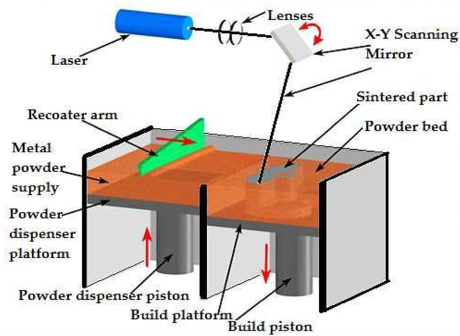
Direct metal laser sintering process –
DMLS follows the basic process sequence for most 3D printing technologies: model, slice, and print layer-by-layer. Once a 3D model is created and sliced with the appropriate software, the code needed for the printer to make the part is supplied to the printer, and the physical process can begin.
To start, the DMLS printer hopper is filled with the desired metal powder. Printer heaters bring the powder to a temperature near the sintering range of the alloy. The printer uses an inert gas, which protects the heated powder and part as it is built.
The build begins with dispensing a thin layer of metal powder onto the build platform. The laser then begins its path for this layer, selectively sintering the powder into a solid. The sequence of dispensing a layer and sintering continues until part completion.
After the part is left to cool, the surrounding loose metal powder is removed from the printer. The last steps include support removal as well as any post-processing needed.
DMLS parts can be treated like metal parts produced by conventional metal working for further processing. This may include machining, heat treatment, or surface finishing.
These process steps are shared with SLM, just with the laser’s power turned up to “melt”.