
Rapid Prototyping 5th Module
Software for RP
STL Files
STL (Stereolithography) is a file format native to the stereolithography CAD software created by 3D Systems. STL has several after-the-fact backronyms such as "Standard Triangle Language" and "Standard Tessellation Language".
• STL was invented by the Albert Consulting Group for 3D Systems in 1987. The format was developed for 3D Systems' first commercial 3D printers. Since its initial release, the format remained relatively unchanged for 22 years. In 2009, an update to the format, dubbed STL 2.0, was proposed.
• This file format is supported by many other software packages; it is widely used for rapid prototyping, 3D printing and computer-aided manufacturing.
• STL files describe only the surface geometry of a three-dimensional object without any representation of color, texture or other common CAD model attributes. The STL format specifies both ASCII and binary representations. Binary files are more common, since they are more compact.
• An STL file describes a raw unstructured triangulated surface by the unit normal and vertices (ordered by the right-hand rule) of the triangles using a three-dimensional Cartesian coordinate system. STL coordinates must be positive numbers, there is no scale information, and the units are arbitrary
Different type of STL file
ASCII STL
An ASCII STL file begins with the line
solid name
where name is an optional string (though if name is omitted there must still be a space after solid). The remainder of the line is ignored and is sometimes used to store metadata (e.g., filename, author, modification date, etc). The file continues with any number of triangles, each represented as follows:
facet normal ni nj nk
outer loop
vertexv1x v1y v1z
vertexv2x v2y v2z
vertexv3x v3y v3z
endloop
endfacet
where each n or v is a floating-point number in sign-mantissa-e-sign-exponent format, e.g., 2.648000e-002. The file concludes with
endsolid name
The structure of the format suggests that other possibilities exist (e.g., facets with more than one loop, or loops with more than three vertices). In practice, however, all facets are simple triangles.
Whitespace (spaces, tabs, newlines) may be used anywhere in the file except within numbers or words. The spaces between facet and normal and between outer and loop are required.
Binary STL
Because ASCII STL files can be very large, a binary version of STL exists. A binary STL file has an 80-character header (which is generally ignored, but should never begin with solid because that may lead some software to assume that this is an ASCII STL file). Following the header is a 4-byte little-endian unsigned integer indicating the number of triangular facets in the file. Following that is data describing each triangle in turn. The file simply ends after the last triangle.
Each triangle is described by twelve 32-bit floating-point numbers: three for the normal and then three for the X/Y/Z coordinate of each vertex – just as with the ASCII version of STL. After these follows a 2-byte ("short") unsigned integer that is the "attribute byte count" – in the standard format, this should be zero because most software does not understand anything else.
Color in binary STL
• There are at least two non-standard variations on the binary STL format for adding color information:
• The VisCAM and SolidView software packages use the two "attribute byte count" bytes at the end of every triangle to store a 15-bit RGB color:
– bits 0 to 4 are the intensity level for blue (0 to 31),
– bits 5 to 9 are the intensity level for green (0 to 31),
– bits 10 to 14 are the intensity level for red (0 to 31),
– bit 15 is 1 if the color is valid, or 0 if the color is not valid (as with normal STL files)
Advantages and Disadvantages
PROS
1. Easy to share and publish
If you look at any site that publishes 3D models, you’ll notice that a lot of them are in STL format. The simplicity of STL files keeps their sizes small. They may lack the fidelity of other file formats, but most 3D printers are similarly limited in the level of detail they can recreate anyway, so it hardly matters.
2. Compatible with practically all 3D modeling and printing software platforms
STL has been widely accepted as the standard file format for models meant for 3D printing, so manufacturers of 3D printers have designed their products to work with it. Almost all 3D modeling software platforms can open STL files, with some even developing a “light” version of their platform meant exclusively for working with STL. With a large user base that relies on the file format, technology for working with STL is likely some of the most mature in the field of 3D design.
3. Acts as the interface between 3D modeling and 3D printing
Full-fidelity 3D models created using CAD software are impractically complex for sharing online, more so for 3D printing. Converting to STL is a way to “simplify” the model to a form that can be easily understood by a printer’s slicer software. There are even some 3D printer models that don’t work with any other file format aside from STL.
· 4. Due to their lack of color and texture, STL files tend to be smaller in size yet faster at processing than other formats. This makes STL a smart choice if you’re printing an object in a single color and material.
CONS
1. Does not contain texture data
A standard STL file merely contains data on the vertices of the triangles that approximate the surface of a 3D model – nothing else. This means that an STL color does not contain color, texture, or material to be used. If you want to print a 3D model using multiple colors or materials, then an STL file is not the best choice.
2. STL files are very hard to modify
A major disadvantage of an STL file is that it can be very hard to edit outside of simple scaling of the model. Since an STL model only contains an approximation of the original 3D model and not the model itself, it’s often easier to start a model from scratch than to modify an existing STL file.
Although we list this as a limitation of STL, some publishers of 3D models actually use this characteristic to their advantage. Since STL models are notoriously hard to work with, it also means that the models they publish cannot be modified. In a way, they retain ownership of their original models, even if the STL version has been published for everyone.
3. Might not catch up with modern 3D printers
We’ve mentioned how the limitation in the fidelity of STL files is tolerable when we consider how today’s 3D printers are similarly limited in resolution. However, this may not be the case moving forward. Even today, modern 3D printers with micron-scale resolution are already being developed. If these 3D printers start to become the industry standard, then tessellated formats like STL may soon find themselves obsolete.
4. Doesn’t contain metadata
Another disadvantage of STL is that the file can’t store metadata. This includes details such as authorship, copyright, and location — all of which are essential to publishing.
Various RP data formats
For 3D formats
· STL (3D systems)
· DFX (AutoDesk)
· CFL (Cubital)
· STEP (ISO)
· RPI (proposed)
For 2D
· SLC (3d Systems)
· SLI (unutar 3d systems)
· HPGL (HP)
· BIN (Sanders)
Overview of solid view in rapid prototyping
• SolidView/Pro RP is the most robust of the SolidView family of products and is designed for companies doing their own rapid prototyping work. SolidView/Pro RP offers all SolidView/Pro features as well as advanced rapid prototyping tools; compound cutting, file repair, z-correction, shelling, offset, and automatic or manual object layout. Optional CAD formats and network licenses are also available for SolidView/Pro RP.
• Just about anywhere you see a 2D engineering drawing, you can use the SolidView family of products instead. By giving everyone involved in the product development and support process a 3D view they can move, scale, rotate and measure, you increase their understanding of the data and improve their productivity. The advantages of SolidView over 2D drawings include:
• Users can view and measure the 3D data
• Valuable engineering time is not wasted on creating 2D drawings
• Users can directly view up-to-date CAD data instead of outdated 2D drawings
• Complex designs and assemblies can be viewed on a low-cost PC, saving plotting paper
and supplies and reducing the security risk of drawing disposal
Magics:
Magics is rapid prototyping software and is a key element of the Magics e-Solution Suite, a full range of market-leading software products that will streamline, automate and boost almost every step in your rapid prototyping and manufacturing (RP&M) process.
Magics rapid prototyping software enables you to import a wide variety of CAD formats and to export STL files ready for rapid prototyping, tooling and manufacturing. Its applications include repairing and optimizing 3D models; analyzing parts; making process-related design changes on your STL files; designing fixtures; documenting your projects; production planning and much more.
Most common input format is DICOM, but other image formats such as: TIFF, JPEG, BMP and Raw are also supported.
Output file formats differ, depending on the subsequent application: common 3D output formats include STL, VRML, PLY and DXF. The 3D files can also be optimized for FEA or CFD and can therefore be exported to Abaqus in INP format, to Ansys in INP, and to Comsol in MPHTXT format. To continue with Computer-aided design, the files can be exported in IGES format or as Point cloud.
Mimics Z or Mimics:
For the first time, doctors, nurses, and technicians who have no previous experience with 3D modelling or 3D printing can create 3D anatomical models from MRI and CT scan images quickly and easily.
Mimics is software specially developed by Materialise for medical image processing. Use Mimics for the segmentation of 3D medical images (coming from CT, MRI, microCT, CBCT, Ultrasound, Confocal Microscopy) and the result will be highly accurate 3D models of your patient’s anatomy. You can then use these patient-specific models for a variety of engineering applications directly in Mimics or 3-matic, or export the 3D models and anatomical landmark points to 3rd party software, like statistical, CAD, or FEA packages.
Use Mimics to:
• Easily and quickly create accurate 3D models from imaging data
• Accurately measure in 2D and 3D
• Export 3D models in STL format for additive manufacturing
• Export 3D models to 3-matic to optimize the mesh for FEA or CFD
Main Features:
• Import DICOM, JPEG, TIFF, BMP, or Raw image data
Industries
• Mimics has been adopted by biomedical engineers and device manufacturers for R&D purposes in various medical industries:
• Cardiovascular
• Craniomaxillofacial
• Orthopedic
• Pulmonology
Applications
Materialise Mimics is a platform to bridge stacked image data to a variety of different medical engineering applications:
• 3D measurements and analyses
• Computer Aided Design: 3-matic, SolidWorks, Pro/E...etc.
• Computational Fluid Dynamics: FLUENT, CFX,...etc.
• Customized implant design
• Finite Element Analysis: ABAQUS, ANSYS,etc.
• Rapid Prototyping: EOS, Stratasys, 3D Systems, Z-Corp, Dimension, Objet, etc.
• Surgical simulation
Magics communicator:
Magics rapid prototyping software enables you to import a wide variety of CAD formats and to export STL files ready for rapid prototyping, tooling and manufacturing. Its applications include repairing and optimizing 3D models; analyzing parts; making process-related design changes on your STL files; designing fixtures; documenting your projects; production planning
Visualise
View STL, IGES*, VDA* and DXF 3d faces*, with fast rotation, zooming and cross sectioning.
Annotate
Add 2D and 3D annotations, shapes, text and bitmaps.
Measure
Easily create 2D drawings from 3D files. Extensive feature recognition allows measuring of distances, radii and angles in 3D. Add tolerances and additional info.
Present
Make a 3D slide show with adjustable colours, shading and transparency.
Internet based software
• A web-based rapid prototyping and manufacturing (RP&M) system offers a collaborative production environment among users and RP&M providers to implement the remote service and manufacturing for rapid prototyping, to enhance the availability of RP&M facilities, and to improve the capability of rapid product development.
• Web-based RP&M systems from both the academic community and industrial bodies all over the world. A number of studies have been performed to explore the architecture, key issues and enabling tools for developing web-based RP&M systems.
• Various Architectures for Web-based RP&M Systems: A variety of frameworks for developing web-based RP&M systems have been proposed. The Tele-Manufacturing Facility (TMF) is probably the first system that provides users with direct access to a rapid prototyping facility over the Internet. TMF allows users to easily submit jobs and have the system automatically maintain a queue. It can also automatically check many flaws in .STL (Stereo lithography) files, and in many cases, fix them. A laminated object manufacturing (LOM) machine was first connected with network, and then the .STL file of a part to be built could be submitted to this machine via a command-line.
Rapid Manufacturing Proccess Optimization:
The parameters of rapid prototyping can be classified as nuisance parameters, constant and control parameters. Nuisance parameters include age of the laser, beam position accuracy, humidity and temperature, which are not controlled in the experimental analysis but may have some effect on a part. Constant parameters include beam diameter, laser focus and material properties, etc. the constant parameters will affect the output of the process and are controllable in a run. These include layer thickness, hatch space, scan pattern, part orientation, shrinkage of the material and beam width compensation, etc. Layer thickness, hatch space, part orientation and depth of cure are the most vital among the control parameters.
Identification of requirements and key manufacturing parameters
• The functional requirements of a manufacturing process include accuracy, strength, buildtime and efficiency of the process. All the manufacturing requirements are also applicable to RP. Surface accuracy is gaining a greater significance as more parts are used as master patterns for secondary manufacturing process. Build time is important in the general context of manufacturing for scheduling and cost estimation.
Layer thickness, hatch space and orientation are the key control parameters for SLS and SLA. These are required indeed process-independent parameters, and can be applied to other processes, such as LOM, FDM, etc. Support structures are essential for SLA and FDM, but they are not needed for LOM and SLS processes.
Factors influencing accuracy
The factors that most influence RP process accuracy can be considered in three groups. The first group includes factors causing errors during the data preparation stage such as STL file generation, model slicing and part build direction. The second group includes factors influencing the part accuracy during the build stage such as process specific parameters. The third group of factors is directly related to the part finishing techniques employed.
Accuracy of a model is influenced by the errors caused during tessellation and slicing at data preparation stage. Decision of the designer about part deposition orientation also affects accuracy of the model
Data preparation errors
a. Errors due to tessellation – during tessellation the surfaces of the CAD models are divided into small triangles. By reducing the size of the triangles, the deviation between the actual surfaces and approximated triangles can be reduced. The resolution of the STL file is controlled by a parameter namely chordal error or facet deviation as show in the figure.
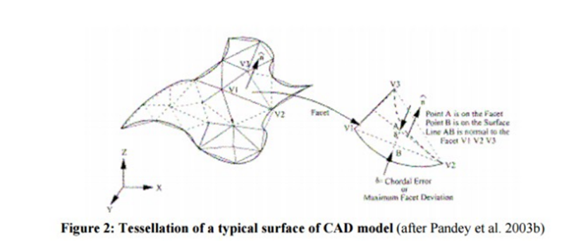
Its been suggested that for the curve with small radius (r) should be tessellated, if its radius is below a threshold radius (r0) which can be considered as one tenth of the part size to achieve maximum chordal error (r/r0).
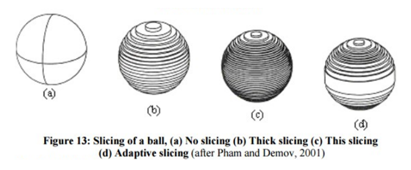
b. Errors due to Slicing – for example error due to replacement of a circular arc with stair steps can be defined as radius of the arc minus length up to the corresponding corner of the staircase i.e cusp height as show in the figure. Maximum error results along Z axis and is equal to slice thickness. Reduction in slice thickness yields drastic improvement in part building time therefore by using slices of variable thicknesses cups height can be controlled below a certain value. Along with this mismatching of height and missing features are two other problems resulting from the slicing. Most of the RP system has the facility to slice
Along with this mismatching of height and missing features are two other problems resulting from the slicing. Most of the RP system has the facility to slice with uniform thickness which gives better accuracy and surface finish without losing important features of the models.
Part building errors:
During part building two types of errors are observed namely curing errors and control errors. Curing errors are due to over or under curing with respect to curing line and control errors are due to variation in layer thickness or scan position control.
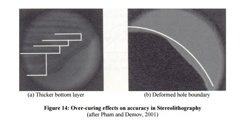
Figure shows the effect of over curing on part geometry and accuracy, Adjustment of chamber temperature and laser power is needed for proper curing and Calibration of the system becomes mandatory to minimize control errors.
Shrinkage also caused dimensional inaccuracy and is taken care by choosing proper scaling in X, Y and Z directions. Polymers are also designed to have almost negligible shrinkage factors.
In Stereolithography and Selective laser sintering process, problem arises with downward facing layers as these layers do not have a layer underneath and are slightly thicker, which generate dimensional error. If proper care is not taken in setting temperatures, curling of the parts can be visualized
Error in finishing, or Part finishing
Some RP applications such as fabrication of exhibition quality models, tooling or master patterns for indirect tool production require additional finishing improving the surface appearance of the part. To achieve this, the stair-step effect on important surfaces has to be removed. Usually, this is done by sanding and polishing RP models, which leads to changes in feature shapes, dimensions and positions.
The model accuracy after finishing operations is influenced mostly by two factors, the varying amount of material that has to be removed and the finishing technique adopted. These two factors determine to what extent the dimensional accuracy of RP models will be reduced during finishing.
Varying amount of material: During the data preparation stage, the RP model shapes are approximated with the corners of stair-steps. Each RP process reproduces the corners and the stair-steps with different resolution. Hence, the amount of material that has to be removed to improve the amount of material to be removed on surfaces of the same model can vary due to the selected part build orientation.
Finishing technique: A number of processes can be employed to finish RP models, for example, wet and try sanding, sand blasting, coating, spraying, infiltration with special solutions, machining, etc. Each technique has specific technological capabilities and can be characterised by the achievable dimensional accuracy and surface roughness.

