
Sensors and Signal Conditioning 1st module
A sensor is a device that detects and responds to some type of input from the physical environment. The specific input could be light, heat, motion, moisture, pressure, or any one of a great number of other environmental phenomena.
Measurement Systems
A system is a combination of two or more elements, subsystems, and parts necessary to carry out one or more functions.
The function of a measurement system is the objective and empirical assignment of a number to a property or quality of an object or event in order to describe it. That is, the result of a measurement must be independent of the observer (objective) and experimentally based (empirical).
For example, if a given object has a property larger than the same property in another object, the numerical result when measuring the first object must exceed that when measuring the second object. One objective of a measurement can be process monitoring: for example, ambienttemperature measurement, gas and water volume measurement, and clinical monitoring.
Another objective can be process control: for example, for temperature or level control in a tank. Another objective could be to assist experimental engineering: for example, to study temperature distribution inside an irregularly shaped object or to determine force distribution on a dummy driver in a car crash.
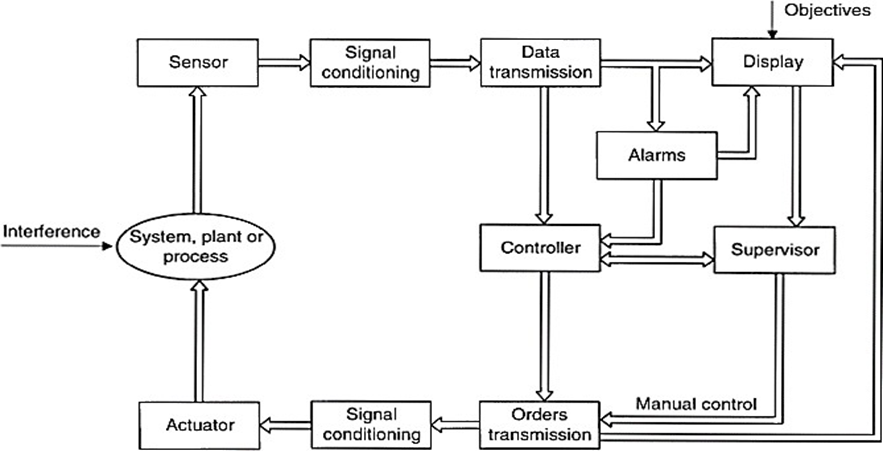
Figure 1.1 shows the functionsand dataflow of a measurement and control system.In general, in addition to the acquisition of information carried out by a sensor, a measurement requires the processing of that information and the presentation of the result in order to make it perceptible to human senses. Any of these functions can be local or remote, but remote functions require information transmission. Modern measurement systems are not physically arranged according to the dataflow in Figure 1.1 but are instead arranged according to their connection to thedigital bus communicating deferent subsystems
1.1 SENSOR CLASSIFICATION
A great number of sensors are available for different physical quantities. In order to study them, the sensors are classified accordingthree primary criterion as follows.
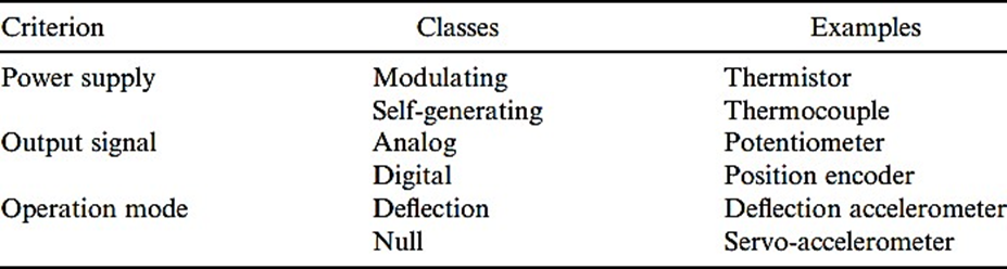
In considering the need for a power supply, sensors are classified as modulating or self generating.
Ø In modulating (or active) sensors, most of the output signal power comes from an auxiliary power source. The input only controls the output. Conversely, in self generating (or passive) sensors, output power comes from the input.
Ø Modulating sensors usually require more wires than self-generating sensors, because wires different from the signal wires supply power.
Ø The presence of an auxiliary power source can increase the danger of explosion in explosive atmospheres.
Ø Modulating sensors have the advantage that the power supply voltage can modify their overall sensitivity. Some authors use the terms active for self-generating and passive for modulating.
In considering output signal classify sensors as, we classify sensors as analog or digital.
Ø In analog sensors the output changes in a continuous way at a macroscopic level. The information is usually obtained from the amplitude, although sensors with output in the time domain are usually considered as analog.
Ø The output of digital sensors takes the form of discrete steps or states. Digital sensors do not require an Analog to Digital Converter, and their output is easier to transmit than that of analog sensors.
Ø Digital output is also more repeatable and reliable and often more accurate. But regrettably, digital sensors cannot measure many physical quantities.
In considering the operating mode, sensors are classified in terms of their function in a deflection or a null mode.
Ø In deflection sensors the measured quantity produces a physical effect that generates in some part of the instrument a similar but opposing effect that is related to some useful variable.
Ø Null-type sensors attempt to prevent deflection from the null point by applying a known effect that opposes that produced by the quantity being measured. There is an imbalance detector and some means to restore balance
1.2 PRIMARY SENSORS
The primary transducer or sensor is the element that is in contact with the pressure pulse, and generally is a displacement transducer, which transduces the pressure wave into a mechanical displacement.
Primary sensors convert measurands from physical quantities to other forms. We classify primary sensors here according to the measurand. Devices that have direct electric output are plain sensors.
Types of Primary sensors:
1. Temperature sensors:Bimetals
2. Pressure sensors
3. Flow velocity and flow-rate sensors,
4. Level sensors,
5. Force and torque sensors,
6. Acceleration and inclination sensors,
7. Velocity sensors,
1.3.1 Temperature sensors: Bimetaals
Temperature conveys the state of a mechanical system in terms of explansion or contraction of thermoelectric emfs
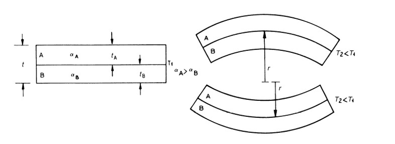
Bimetallic strips are used as thermal switch in controlling the temperature or heat in a manufacturing process or system. It contains two different metal strips bonded together. The metals have different coefficients of expansion. On heating the strips bend into curved strips with the metal with higher coefficient of expansion on the outside of the curve. Figure.1.3.1 shows a typical arrangement of a bimetallic strip used with a setting-up magnet. As the strips bend, the soft iron comes in closer proximity of the small magnet and further touches. Then the electric circuit completes and generates an alarm. In this way bimetallic strips help to protect the desired application from heating above the pre-set value of temperature.
Figure 1.3.1 A bimetal consists of two metals with dissimilar thermal expansion coefficients, which deformswhen temperature changes.
Bimetal strips are also used as actuators to directly open or close contacts (thermostats, on-off controls, starters fluorescent lamps) and for overcurrent protection in electric circuits
1.3.1 Pressure Sensors
A pressure sensor is a device for pressure measurement of gases or liquids. Pressure is an expression of the force required to stop a fluid from expanding, and is usually stated in terms of force per unit area. A pressure sensor usually acts as a transducer; it generates a signal as a function of the pressure imposed
Pressure sensors are used for control and monitoring in thousands of everyday application
Liquid-column U-tube manometer
The simplest form of manometer consists of a U-shaped glass tube containing liquid. It is used to measure gauge pressure and are the primary instruments used in the workshop for calibration.
The principle of the manometer is that the pressure to be measured is applied to one side of the tube producing a movement of liquid, as shown in figure above. It can be seen that the level of the filling liquid in the leg where the pressure is applied, i.e. the left leg of the tube, has dropped, while that in the right hand leg as risen. A scale is fitted between the tubes to enable us to measure this displacement.
Let us assume that the pressure we are measuring and have applied to the left hand side of the manometer is of constant value. The liquid will only stop moving when the pressure exerted by the column of liquid, h is sufficient to balance the pressure applied to the left side of the manometer, i.e. when the head pressure produced by column” h” is equal to the pressure to be measured.
Knowing the length of the column of the liquid, H, and density of the filling liquid, we can calculate the value of the applied pressure.
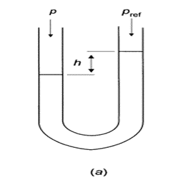
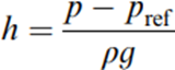
Figure 1.3.2 a compares the pressure to be measured with a reference pressure and yields a difference h of liquid level.
where ρ is

C-shaped Bourdon tube.
It is basically consisted of a C-shaped hollow tube, whose one end is fixed and connected to
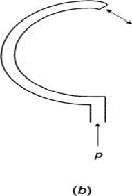
the pressure tapping, the other end free, as shown in fig. The cross section of the tube is elliptical.
When pressure is applied, the elliptical tube (Bourdon tube) tries to acquire a circular cross section; as a result, stress is developed and the tube tries to straighten up. Thus the free end of the tube moves up, depending on magnitude of pressure. A deflecting and indicating mechanism is attached to the free end that rotates the pointer and indicates the Pressure reading. The materials used are commonly Phosphor Bronze, Brass and Beryllium Copper
Twisted Bourdon tube.
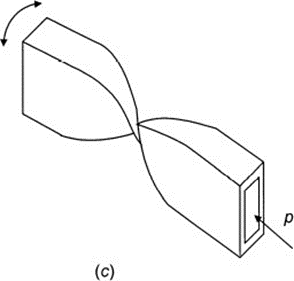
Helical is a bourdon tube wound in the form of helix. It allows the tip movement to be converted to a circular motion.
By installing a central shaft inside the helix along its axis and connecting it to the tip, the tip movement become a circular motion of the shaft.
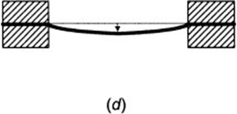
Diaphragm
Diaphragm pressure gauges are used to measure gases and liquids. They cover measuring spans from 10 mbar to 40 bar. The measuring element consists of one circular diaphragm clamped between a pair of flanges. The positive or negative pressure acting on these diaphragms causes deformation of the measuring element. The magnitude of the deformation is proportional to the pressure to be measured, and it is coupled to the pointer mechanism.
Pressure sensing capsules
The pressure-sensing capsule adapts the diaphragm sensing principleto allow measurement of low pressures that would otherwise require an impractically large and thin diaphragm. The capsule comprises two diaphragms, welded at the edge, to allow the pressure media to act on both simultaneously. The resulting structure displays twice the displacement, relative to the pressure applied, compared to a single-diaphragm.
Pressure sensing can be done using a single capsule, as shown in the first diagram below, or using a stack of capsules.
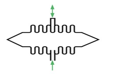
Bellows sensing elements
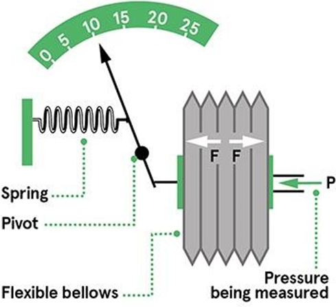
The bellows sensing element is a container that expands in response to the force applied by the pressure medium within. The bellows is typically made from a metal such as phosphor bronze, brass, beryllium copper, or stainless steel. It can be machined from solid stock, rolled from tube, or fabricated with aseries of welded annular rings.
An internally mounted - or external - spring enhances the bellows’ response to positive- and negative-going pressure changes. As a result, the deflection characteristics are a combination of the mechanical properties of the bellows, and those of the spring.

Flow Velocity and Flow-Rate Sensors
A flow sensor (more commonly referred to as a “flow meter”) is an electronic device that measures or regulates the flow rate of liquidsand gasses withinpipes and tubes The
differences in pressure(i.e. the vortices) generated by the latch are measured to determine the flow rate.
Orifice Plate
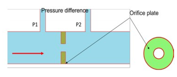
Figure shows a schematic of Orifice plate device. It has a disc with a hole at its center, through which the fluid flows. The pressure difference is measured between a point equal to the diameter of the tube upstream and a point equal to the half the diameter downstream. Orifice plate is inexpensive and simple in construction with no moving parts. It exhibits nonlinear behavior and does not work with slurries. It has accuracy of ± 1.5%.
Flow Nozzle
When a flow nozzle is placed in a pipe carrying whose rate of flow is to be measured, the flow nozzle causes a pressure drop which varies with the flow rate.
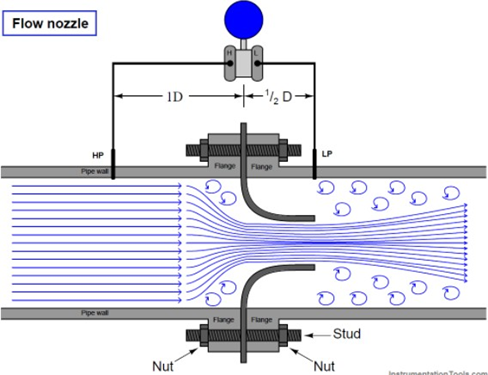
The fluid whose flow rate is to be measured enters the nozzle smoothly to the section called throat where the area is minimum.
Before entering the nozzle, the fluid pressure in the pipe is p1. As the fluid enters the nozzle, the fluid converges and due to this its pressure keeps on reducing until it reaches the minimum cross section area called throat. This minimum pressure p2 at the throat of the nozzle is maintained in the fluid for a small length after being discharged in the down stream also.
The differential pressure sensor attached between points 1 and 2 records the pressure difference (p1-p2) between these two points which becomes an indication of the flow rate of the fluid through the pipe when calibrated.
Basics of Venturi Flow Meter
A venturi tube contains a throat which is smaller in a diameter to the pipeline, into which it
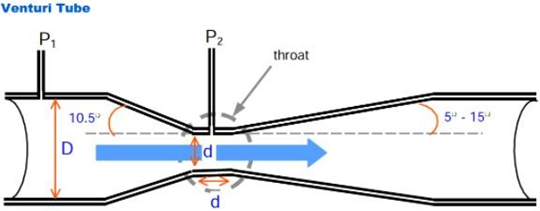
fits. The restriction diameter should not be less than 0.224 D, and not more than 0.742 D where D is the nominal bore diameter of the pipe.
When the fluidflows through it, the
pressure at the throat is lower than the upstream pressure (because of increased kinetic energy due to increased velocity, ½ mv2) and the consequent reduction in flow energy (Ef = P • . v).
The flow rate isproportional to the pressure difference, P1 -– P2.
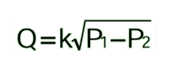
Rotatometer
The rotameter in Figure 1.17 applies this method. It consists of a uniform conic section tube and a grooved float inside it that is dragged by the fluid to a height determined by its weight and the flow. The fluid gas or liquid flows upward. When the flow increases, the float rises, thus allowing an increased annular pass section and keeping the pressure difference between both ends constant. The displacement of the float indicates the fluid flow rate
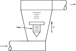
1.3.4 Level Sensors
Dipsticks are simple level sensors, but cannot easily provide an electric signal. Floats, based on Archimedes' buoyancy principle, convert liquid level to force or displacement (Figures a and b).
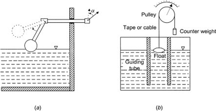
Principle of Operation: A liquid level control system by using a float sensor works on the principle of buoyancy, which states, “A float immersed in a liquid is buoyed towards upward direction by an applied equal force to the weight of the displaced liquid”. As a result, the body drives partially and gets submerged upon the liquid surface and covers the same distance the liquid level moves.
Acceleration and Inclination Sensors
Acceleration Sensors:
They are frequently used to determine the speed and the position of various vehicles, such as planes, ships, cars, robots, etc.
They can be classified according to the physical principlethey use:
Ø Direct measurement of a force (piezoelectric sensor,sensor with force balance).
Ø Indirect measurement, by means of displacement or deformation of a sensingelement.
The inertial force can be measured either through strain (if deformation is minimum) or through the deformation of elastic element.
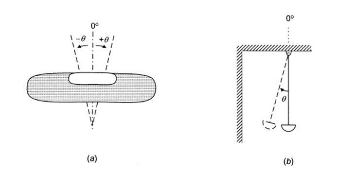
Inclinometer Sensors:
Inclinometers, also called tilt sensor, clinometers or slope sensors, are designed to measure the angle of an object with respect to the force of gravity. These tilt or level meters determine the pitch and/or roll angle and output these values via the appropriate electrical interface.
An inclinometer is a sensor used to measure the magnitude of the inclination angle or deformation of any structure. The bent is either depicted in percentage or degrees concerning gravity.
Inclinometer sensors are of different types. Each inclinometer system requires a combination of equipment and sensors to measure and collect data.
MATERIALS FOR SENSORS
Conductors, Semiconductors and Dielectrics
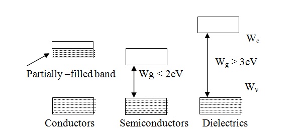
Physical properties of solids, and their electric properties, are determined by the degree of filling of the energy bands rather than bytheir formation. From this point of view all crystalline bodies can be dividedinto two different groups.
Conductors
The first group includes substances having a partially filled band in their energy spectrum above the completely filled energy bands. As was mentioned above a partially filled band is observed in alkali metals whose upper band is formed by unfilled atomic levels, and in alkali- earthcrystals. All substances belonging to this group are conductors.
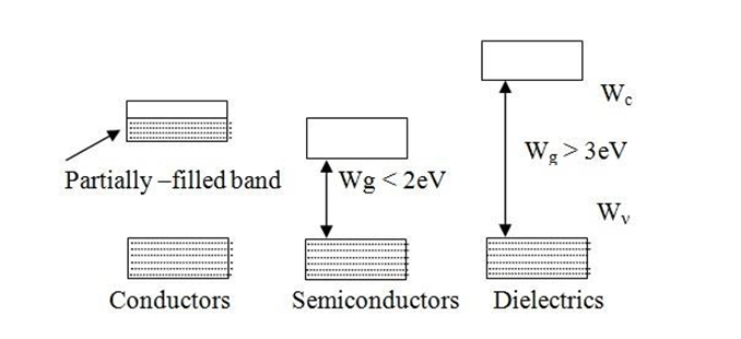
Semiconductors and Dielectrics
The second group comprises of substances with absolutely empty bands above completely filled bands. This group also includescrystals with diamondshaped structures such as Silicon, Germanium, gray tin, and Diamonditself. This second group includessemiconductors and dielectrics. The uppermost filled band in these crystals is called valence band and the first empty band above it the conduction band. The upper level of the valence band is called the top of the valence band and is denoted by Wv. The lowest level of the conduction band is called the bottomof conduction band and denoted by Wc.
The division into semiconductors and Dielectrics is quite arbitrary and is determined by the width Wg of the forbidden energy gap separating the completely filled band from the empty band. Substances with a forbidden gap of Wg <2 eV belong to the semiconductor sub-group. . Substances for which Wg > 3eV belong to dielectrics.
Magnetic materials
Magnetic materials are materials studied and used mainly for their magnetic properties. The magnetic response of a materials is largely determined by the magnetic dipole moment associated with the intrinsicangular momentum, or spin, of its electrons. A material’s response to an applied magnetic field can be characterized as diamagnetic, paramagnetic,ferromagnetic or antiferromagnetic.
1.3 MICROSENSOR TECHNOLOGY
Thick-Film Technology
In the 1970s thick film started to gain popularity. Today, these are by far the most used resistors in electrical and electronic devices. They come usually as chip resistor (SMD), and have the lowest cost compared to any other technology.
The resistive material is a special paste with a mixture of a binder, a carrier, and the metal oxides to be deposited. The binder is a glassy frit and the carrier exists of organic solvent systems and plasticizers. Modern resistor pastes are based on oxides of ruthenium, iridium and rhenium. This is also referred to as a cermet (Ceramic – Metallic). The resistive layer is printed onto a substrateat 850°C. The substrate is often 95% alumina ceramic. After the firing of the paste on the carrier, the film becomes glasslike, which makes it well protected against moisture. The complete firing process is schematically depicted in the graph below. The thickness is in the order of 100 micrometer. This is approximately 1000 times more than thin film. Unlike thin film, this process is additive. This means that the resistive layers are added sequentially to the substrate to create the conducting patterns and resistance values.
Thin Film Technology
The resistive layer is sputtered (vacuum deposition) onto a ceramic base. This creates a uniform metallicfilm of around 0.1 micrometre thick. Often an alloy of Nickel and Chromium is used (Nichrome). They are producedwith different layer thicknesses to accommodate a range of resistance values. The layer is dense and uniform, which makes is suitable to trim the resistance value by a subtractive process. With photo etching or by laser trimming patterns are created to increase the resistive path and to calibrate the resistance value. The base is often alumina ceramic, silicon or glass. Usually thin film is produced as a chip or smd resistor, but the film can also be applied onto a cylindrical base with axial leads. In this case, more often the term metal film resistor is used.
Thin film is usually used for precision applications. They feature relatively high tolerances, low temperature coefficients and low noise. Also for high frequency applications thin film performs better than thick film. Inductance and capacitance are generally lower. The parasitic inductance of thin film can be higher if it is executed as a cylindrical helix (metal film resistor). This higher performance comes with a cost, which can be factors higher than the price of thick film resistors. Typical examples where thin film is used are medical equipment, audio installations, precision controlsand measurement devices
1.4 MAGNETORESISTOR
The magnetoresistor is used for determining the presence of a magnetic field their strength and the direction of the force.It is made of the indium antimonide or indium arsenide semiconductor material.
WorkingPrinciple of Magnetoresistor
It works on the principle of electrodynamics, which states that the force acting on the current place in the magnetic field changes their direction. In the unavailability of the magnetic field,the charge carriers of the magneto resistor move in the straight path
In the presence of the magnetic field, the direction of the current becomes changes, and it flows in the opposite direction. The indirect path of the current increases the mobility of their charge carrier which causes the collision.
The collision increases the loss of energy in the form of heat. This heat increases the resistance of the magnetoresistor. The currentof very small magnitude flows in the magnetoresistor becauseof few free electrons.
The deflection of the magnetoresistor electrons depends on their mobility. It is more in the semiconductor material as compared to the metals. The mobility of the indium arsenides or indium antimonides is approximately 2.4m2/Vs.
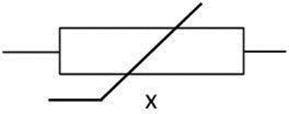
1.5 LIGHT DEPENDENTRESISTOR
A Light Dependent Resistor (LDR) is also called a photoresistor or a cadmium sulfide (CdS) cell. It is also called a photoconductor. It is basicallya photocell that works on the principleof photoconductivity.
LDR Structure and Working
The basic structure of an LDR is shown below.

The snake like track shown below is the Cadmium Sulphide (CdS) film which also passes through the sides. On the top and bottom are metal films which are connected to the terminal leads. It is designed in such a way as to provide maximum possible contact area with the two metal films.
The structure is housed in a clear plastic or resin case, to provide free access to external light. As explained above, the main component for the construction of LDR is cadmium sulphide (CdS), which is used as the photoconductor and contains no or very fewelectrons when not illuminated.
In the absence of light it is designed to have a high resistance inthe range of megaohms. As soon as light falls on the sensor, the electrons are liberated and the conductivity of the materialincreases.
When the light intensityexceeds a certainfrequency, the photonsabsorbed by the semiconductor give band electronsthe energy required to jump into the conduction band. This causes the free electrons or holes to conduct electricity and thus droppingthe resistance dramatically (< 1 Kiloohm).
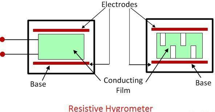
Resistive Hygrometer
The conducting film of the resistive hygrometer is made by the lithium chloride and the carbon. The conducting film places between the metal electrodes. The resistance of the conducting film varies with the change in the value of humidity present in the surrounding air.
The moisture absorbs by the lithium chloride will depend on the relative humidity. If the relative humidity is high, the lithium chloride will absorb more moisture and their resistance decreases.
The change in the value of resistance is measured by applying the alternating current to the bridge. The direct current is not used in the bridge as they breakdowns the layer of lithium chloride. The obstructions occur in the flows of current shows the value of resistance or the value of relative humidity.
Ø This hygrometertype utilizes resistivity change with respect to humidityfor relative humidity measurement. The figure-1depicts Resistive Hygrometer.
Ø It uses hygrometric salt material such as LiCl (LithiumChloride) for this purpose.
Ø Resistance of this material changes to wide range from 104 to 109 Ohms with humidity change from 100% to 0% respectively.
Ø Higher relative humidity will result into more moisture absorption by LiCl material.This will lower the resistance of the material and vice versa.
LIQUID CONDUCTIVITY SENSORS
Conductivity basics
A fluid’s ability to conduct electrical current is a result of positively and negatively charged particles present in and moving within the fluid, resulting in electrical conductance. Just as electrons move through a solid wire to conduct electrical current, current flow in a fluid is transported by ions in solution. The morefree ions present, the higher the conductivity. Fewer free ions lower fluid conductivity, or inversely increase resistivity.
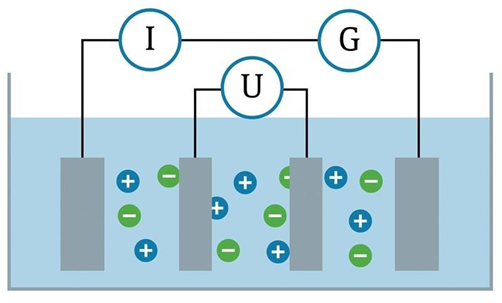
Four-electrode conductivity sensors address a broader range of measurement. A four- electrodeconductivity probe uses the same principles of a conductive probe but adds two additional electrodes to the sensor (see Figure 3).
The outer two electrodes operate on the same principle as a conductive sensor in which an alternating voltage is applied to these electrodes, and the resulting current is measured.As the conductivity of the fluid increases and polarization effects begin to occur, the two additional inner electrodes measure the voltage and compensate the current measurement for any polarization effect

