
Sensors and Signal Conditioning 2nd Module
2.1 CAPACITIVE SENSORS
2.1.1 Variable Capacitor
A capacitor consists of two electric conductors separated by a dielectric (solid, liquid, or gas) or a vacuum. The relationship between the charge Q and the difference in voltage V between them is described by means of its capacitance, C= Q/V. This capacitance depends on the geometrical arrangement of the conductors and on the dielectric material between them,
For example, for a capacitor formed by n equal parallel plane plates having an area A, with a distance d between each pair, and an interposed material with a relative dielectric constant ϵr, the capacitance is
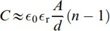
where ϵ0=8:85 pF/m is the dielectric constant for vacuum.
Figure.1 shows how to reduce fringe effects without changing geometrical relations. It consists of using guards that are connected to a constant voltage so that electric field flux lines remain confined into the volume defined by the sensing electrode.
Capacitive sensors have high output impedance. This certainly decreases when the supply frequency increases, but stray capacitances also cause impedance decrease at higher frequencies.
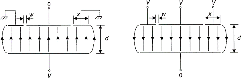
Figure 2 shows some sensor configurations for capacitive displacement sensors based on a change of area (a-e), electrode separation ( f ), or the dielectric g; h. Change in dielectric is not common becauseof the mechanical problems posed by its manufacturing and operation. Changes based on a variation of the distance betweenelectrodes is common for measuring large and very small displacements. Changes based on a variation of area is more common for medium-range displacement measurement, 1 cm to 10 cm.
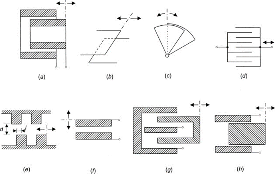
Figure 2 Different arrangements for capacitive sensors based on (a-e) a variation of area, ( f ) plate separation, and (g, h) dielectric.
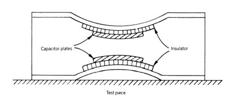
Figure: 3 The capacitance strain guage consists of two arched flexible strips bonded on the test piece. The horizontal stress in the test piece changes the bowing of the strips and hence the vertical gap between the capacitor plates.
2.1.2 Differential Capacitor
A differential capacitor consists of two variable capacitors so arranged that they undergo the same change but in opposite directions.
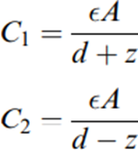
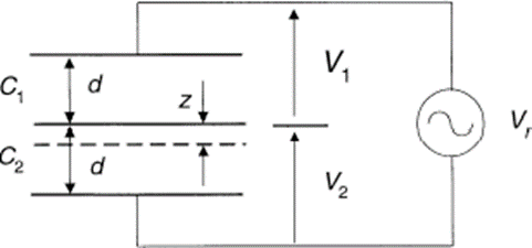
Figure 5 Differential capacitor based on the variation of the distancebetween plates. The respective drop in voltage across each capacitor is
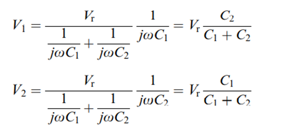
Substituting for the capacitance their values as given equation yields
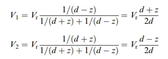
When we subtract both voltages we obtain
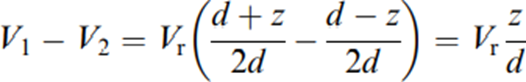
Therefore, an appropriate output signal conditioning yields a linear output that has an increased sensitivity compared to a single capacitor.
If the measurand changes the area of C1 and C2 instead for example, as in Figure 6 we have
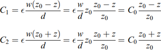
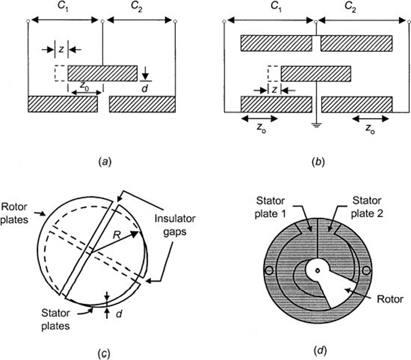
Figure: 6 Differential capacitors based on the variation of effective plate area.
Here too, measuring the difference between capacitances yields a result proportional to z. The sensor in Figure 6 b has the same equation.
Figure 6 c shows a linear rotary differential capacitance sensor (LRDC) . It consists of two equal-size parallel circular plates, each divided by an insulating gap along a diameter
The angular displacement sensor in Figure 6d has two fixed plates and one movable plate (rotor). This defines two capacitors whose sum is constant but whose values increase and decrease by the same amount when the rotor turns.
2.2 INDUCTIVE SENSORS
2.2.1 Variable Reluctance Sensors
Variable reluctance speed sensors measure the position and speed of moving ferrous objects. Their versatility, simplistic design, and relatively low cost of manufacturability make them attractive for use in the aerospace industries. The variable reluctance sensor consists of a permanent magnet and a ferromagnetic pole piece surrounded by a coil of wire. The sensor generates an analog voltage output signal when a ferromagnetic material passes by the tip of the pole piece. The magnitude of the induced voltage is therefore a direct function of the flux linkage in the coil as a function of time. The voltage signal is sent to the control unit where it is often converted to a digital signal to support the controlling function.
The reluctance of a circuit indicates the amount of magnetic flux it links, due to an electric current. If it is a current flowing along the circuit itself, we call it self inductance L. Otherwise we call it mutual inductance M.
The inductance can be expressed as

Figure: 8 Variable reluctance sensor with magnetic flux paths in air and in a ferromagnetic material.
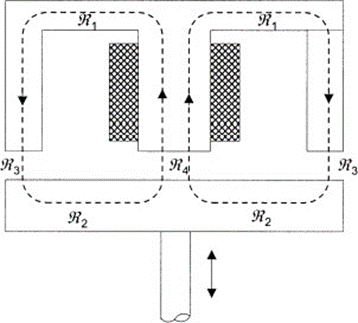
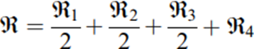
Different configurations for variable reluctance sensors. (a) to (d ) rely on a variation in the number of coil turns; (e) to (g) rely on a magnetic core movement; (h) and (i) rely on a gap variation. The sensors in (c), (d ), ( f ), (g), and (i) are differential.
2.2.1 Eddy Current Sensors
The inductive reactance of a coil supplied by alternating current decreases if a nonmagnetic conductive target is placed inside its magnetic field. This is because the varying magnetic field induces eddy currents on the target surface that produce a secondary magnetic field, which induces an opposing voltage in the coil. The closer the target is to the coil, the larger the change in impedance. Ferromagnetic target materials first increase the coil reactance because of the magnetic field increase resulting from their higher permeability. However, if eddy currents are strong enough to overcome that effect, the coil inductive reactance decreases.
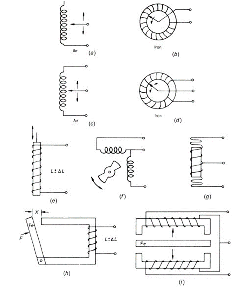
Figure 4.13 (a) Eddy current proximity sensor. (b) Eddy current displacement sensor.
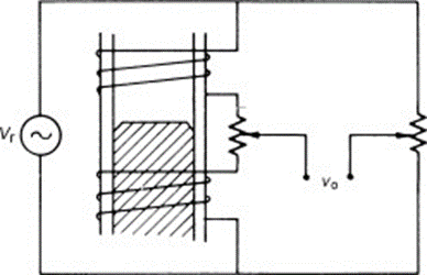
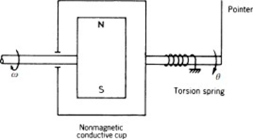
Figure 14 Liquid metal level measurement based on eddy currents. Figure 15 Drag-cup-type eddy current tachometer.
Figure 14 shows a system for liquid metal level measurement. The tube walls are from nonmagnetic steel.The inductance of each coil depends on eddy currentsinduced in the liquid and therefore changeswhen the level does.
Figure 15 shows a drag cup tachometer, where we measure the velocity of a shaft that spins a magnet. The magnet induces eddy currents in the non-ferromagnetic conductive cup, which produces its own magnetic field that interacts with that of the magnet. The cup is held by a torsion spring that twists to an angle at which its torque balances the dragging torque, thus converting a speed into a torque. The twist angle is given on a scale. This sensor has a second order dynamic response.
LVDT
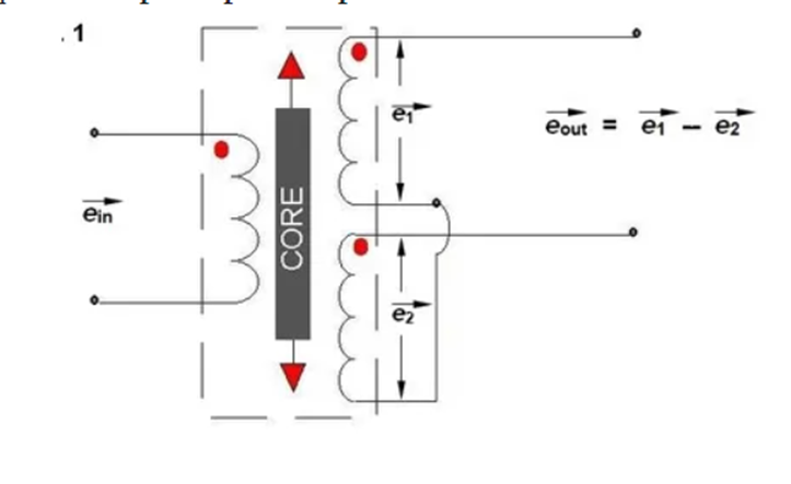
The term LVDT stands for the Linear Variable Differential Transformer. It converts the linear motion into the electrical signal.
Construction of LVDT
Main Features of Construction
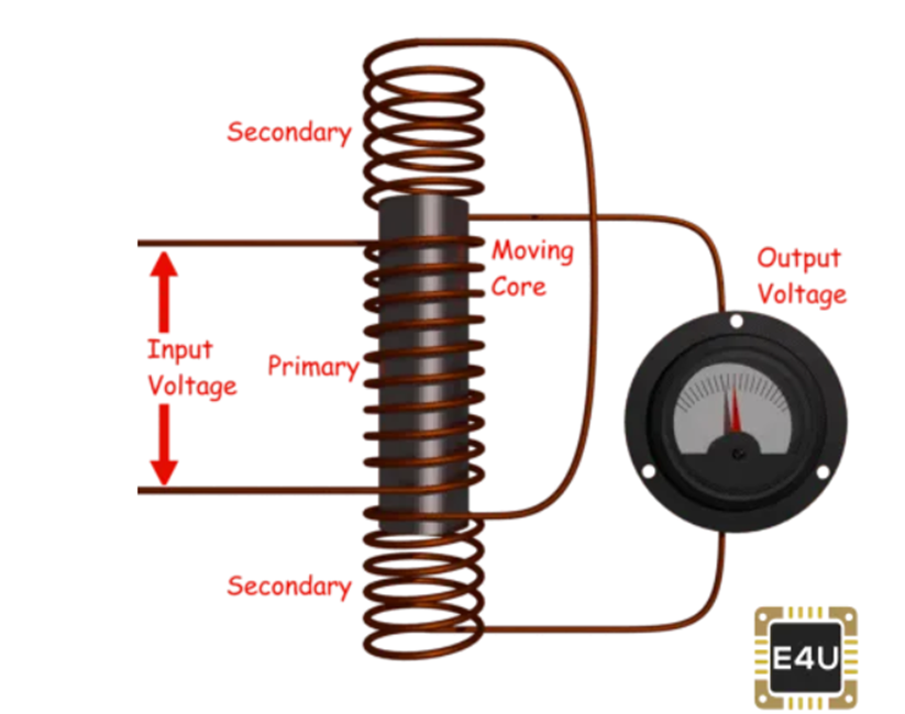
- The transformer consists of a primary winding P and two secondary windings S1 and S2 wound on a cylindrical former (which is hollow in nature and contains the core).
- Both the secondary windings have an equal number of turns, and we place them on either side of primary winding
- The primary winding is connected to an AC source which produces a flux in the air gap and voltages are induced in secondary windings.
- A movable soft iron core is placed inside the former and displacement to be measured is connected to the iron core.
- The iron core is generally of high permeability which helps in reducing harmonics and high sensitivity of LVDT.
- The LVDT is placed inside a stainless steel housing because it will provide electrostatic and electromagnetic shielding.
- The both the secondary windings are connected in such a way that resulted output is the difference between the voltages of two windings.
Principle of Operation and Working
As the primary is connected to an AC source so alternating current and voltages are produced in the secondary of the LVDT. The output in secondary S1 is e1 and in the secondary S2 is e2. So the differential output is,
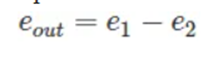
This equation explains the principle of Operation of LVDT.
Now three cases arise according to the locations of core which explains the working of LVDT are discussed below as,
- CASE I When the core is at null position (for no displacement)
When the core is at null position then the flux linking with both the secondary windings is equal so the induced emf is equal in both the windings. So for no displacement the value of output eout is zero as e1 and e2 both are equal. So it shows that no displacement took place. - CASE II When the core is moved to upward of null position (For displacement to the upward of reference point)
In the this case the flux linking with secondary winding S1 is more as compared to flux linking with S2. Due to this e1 will be more as that of e2. Due to this output voltage eout is positive. - CASE III When the core is moved to downward of Null position (for displacement to the downward of the reference point). In this case magnitude of e2 will be more as that of e1. Due to this output eout will be negative and shows the output to downward of the reference point.
Variable Transformer:
Synchros:
A synchro (also known as selsyn and by other brand names) is, in effect, a transformer whose primary-to-secondary coupling may be varied by physically changing the relative orientation of the two windings.
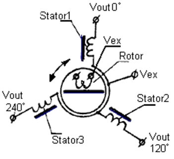
On a practical level, synchros resemble motors, in that there is a rotor, stator, and a shaft. Ordinarily, slip rings and brushes connect the rotor to external power. A synchro transmitter's shaft is rotated by the mechanism that sends information, while the synchro receiver's shaft rotates a dial, or operates a light mechanical load. Single and three-phase units are common in use, and will follow the other's rotation when connected properly. One transmitter can turn several receivers; if torque is a factor, the transmitter must be physically larger to source the additional current.
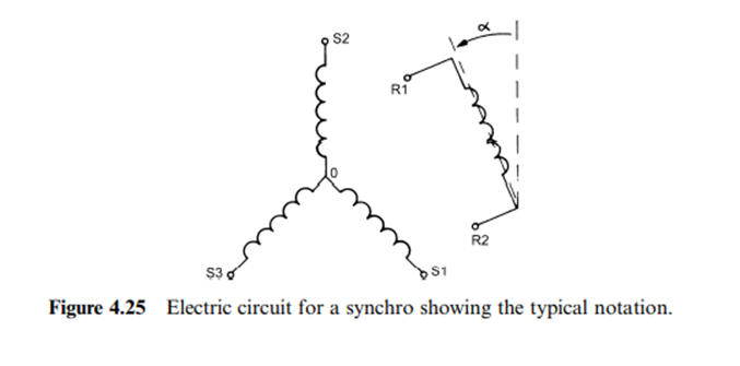
Single phase units have five wires: two for an exciter winding (typically line voltage) and three for the output/input. These three are bussed to the other synchros in the system, and provide the power and information to align the shafts of all the receivers. Synchro transmitters and receivers must be powered by the same branch circuit, so to speak; the mains excitation voltage sources must match in voltage and phase. The safest approach is to bus the five or six lines from transmitters and receivers at a common point. Different makes of selsyns, used in interlock systems, have different output voltages. In all cases, three-phase systems will handle more power and operate a bit more smoothly
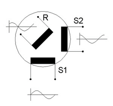
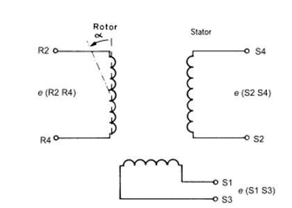
Resolvers:
Resolves are another type of variable transformer, similar to synchors but with winding at 90 degree both in the stator and in the rotor. The format for angle reperesentation is different and it use two voltage instead of three
The resolver works on the principle of an electrical transformer. These transformers use copper windings in stator and rotor. Based on the rotor’s angular position, the inductive coupling of the windings will be changed. The resolver energizes by using an AC signal and the output of this can be measured to provide an electrical signal.
Generally, it includes three windings like one primary and two secondaries. These are designed with the help of copper wire on the stator. The primary winding functions like the i/p for an AC signal whereas each of the secondary winding is used as output. In this, the stationary part is designed with iron or steel.
Depending on intended application they are connected in different forms and the device receives different names.
In vector resolvers, there is a winding on the rotor that acts as a primary and two winding on the stator that acts as secondaries
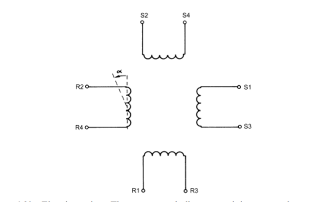
In electrinc resolver as shown in fig below there are also two winding on the rotor at 90 degree ad two winding around the stator also at 90. We can use only one of the primary windings, on the rotor or on the stator.
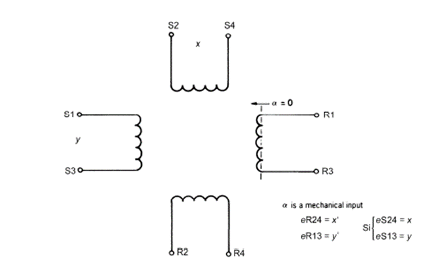
Another application is the rotation of rectangular axes as shown in fig below
Inductosyn: Inductosyn is the trademark of a kind of variable transformer that differes from the previous ones. It can be realized not only in rotary forms by also in linear forms. It cosnists of precision printer circuit patterns with parallel hairpin turns repeated along a flat bar or radial hairpin turns on the flat surface of a disk
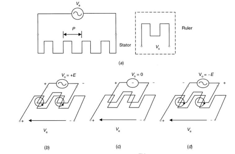
In Figures 1A, 1B, and 1C, winding W2 moves relative to stationary winding W1. Application of an AC excitation signal, V1, to the winding on one element will cause a current flow in that winding which simultaneously induces a corresponding current flow and output voltage, V2, in the winding of the second element.
See Figure 1A. The amplitude and phase of this induced voltage depends on the relative positions of the winding conductors. In Figure 1A, the induced voltage V2 is at maximum amplitude when the winding conductors W2 of one element are exactly aligned with the winding conductors W1 of the other element.
In Figure 1B, the induced voltage, V2, passes through zero when the winding conductors, W2, of one element are midway between the winding conductors, W1, of the other element. The distance moved by W2, from the position shown in Figure 1A to that shown in Figure 1B, is P/4.
In Figure 1C, the induced voltage reaches a maximum amplitude of opposite phase when the winding conductors of both elements are in their next exactly aligned position. For simplicity, the phase reversal is shown as a change in polarity in Figure 1C. The signal forms shown in the circles in Figure 1 are indicative of those that would be observed on an oscilloscope connected to the output winding. Winding W2 moved a distance P/2, between the positions shown in Figures 1A and 1C.
2.3 ELECTROMAGNETIC SENSORS
Electromagnetic Flowmeters
Electromagnetic flowmeters rely on a conductive, nonmagnetic liquid that moves inside an exciting magneticfield created by two externalcoils. Then a small inducedvoltage (1 mV at 1 m/s) result is detected by two electrodes placed at 90 with respect to the flow and the field, as shown in Figure.
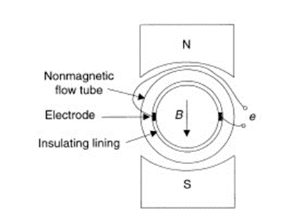
Figure: In an electromagnetic flowmeter, the magnetic field is vertical, the output electric field is horizontal, and the flow is into the page.
The output voltage is proportional to liquid flow only when the velocity profile is symmetric with respect to the flow axis and the magnetic field is uniform in the cross section that includes the electrodes. The dependence of the output voltage on the velocity profile depends on the size of the electrodes. In principle, the larger the electrodes, the better the system works. To prevent the electrodes from getting dirty and from deteriorating, they may be covered by an insulating material, thus resulting in a capacitive coupling to the liquid and an increased output impedance. Alternatively, they can be externally cleaned by ultrasound. The pipe must be completely filled for the measure to be valid.
The pipe must be nonmetallic and nonmagnetic so that the exciting magnetic field is not distorted, and it must have an inner lining with a wear-resistant material.
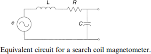
Search coil magnetometer
The search coil magnetometer or induction magnetometer, based on an inductive sensor (also known as inductive loop and inductive coil), is a magnetometer which measures the varying magnetic flux. An inductive sensor connected to a conditioning electronic circuit constitutes a search coil magnetometer. It is a vector magnetometer which can measure one or more components of themagnetic field.
A classical configuration uses three orthogonal inductivesensors. The search-coil magnetometer can measure magneticfield from mHz up to hundreds of MHz.
Principle
The inductivesensor is based on Faraday'slaw of induction. The temporalvariation of the Magnetic Flux ϕ through a N turns circuitwill induce a voltage е which follows
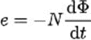
which can be expressed in a simpler way
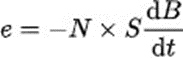
Hall effect Sensors
Hall Effect Sensors are devices which are activated by an external magnetic field. We know that a magnetic field has two important characteristics flux density, (B) and polarity (North and South Poles).
The output signal from a Hall effect sensor is the function of magnetic field density around the device. When the magnetic flux density around the sensor exceeds a certain pre-set threshold, the sensor detects it and generates an output voltage called the Hall Voltage, VH. Consider the diagram below.
Hall Effect Sensor Principles
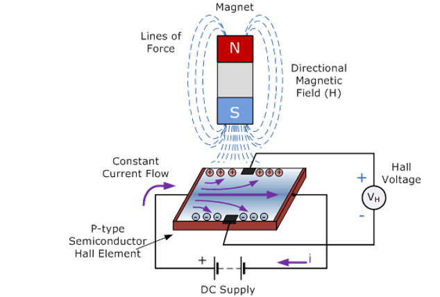
Hall Effect Sensors consist basically of a thin piece of rectangular p-type semiconductor material such as gallium arsenide (GaAs), indium antimonide (InSb) or indium arsenide (InAs) passing a continuous current through itself
Hall Effect Sensors are available with either linear or digital outputs. The output signal for linear (analogue) sensors is taken directly from the output of the operational amplifier with the output voltage being directly proportional to the magnetic field passing through the Hall sensor. This output Hall voltage is given as:
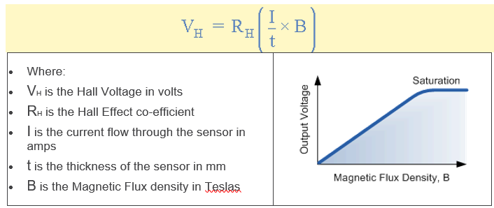
Linear or analogue sensors give a continuous voltage output that increases with a strong magnetic field and decreases with a weak magnetic field. In linear output Hall effect sensors, as the strength of the magnetic field increases the output signal from the amplifier will also increase until it begins to saturate by the limits imposed on it by the power supply. Any additional increase in the magnetic field will have no effect on the output but drive it more into saturation.
Digital output sensors on the other hand have a Schmitt-trigger with built in hysteresis connected to the op-amp. When the magnetic flux passing through the Hall sensor exceeds a pre-set value the output from the device switches quickly between its “OFF” condition to an “ON” condition without any type of contact bounce.
This built-in hysteresis eliminates any oscillation of the output signal as the sensor moves in and out of the magnetic field. Then digital output sensors have just two states, “ON” and “OFF”.

