Sensors and Signal Conditioning 4th Module
INTRODUCTION: -
We distinguish here three classes of digital sensors. The first yields a digital version of the measurand. This group includes position encoders.
The second group relies on some physical oscillatory phenomenon that is later sensed by a conventional modulating or generating sensor. Sensors in this group are sometimes designated as self-resonant, variable-frequency, or quasi-digital sensors, and they require an electronic circuit (a digital counter)in order to yield the desired digital output signal.
The third group of digital sensors use modulating sensors included in variable electronic oscillators. Because we can digitally measure the oscillation frequency, these sensors do not need any ADC either.
Silicon technology has achieved circuit densities that permit the fabrication of sensors that integrate computation and communication capabilities, termed intelligent or smart sensors.
4.1 POSITION ENCODERS
Linear and angular position sensors are the only type of digital output sensors that are available in several different commercial models.
4.1.1 INCREMENTAL POSITION ENCODERS
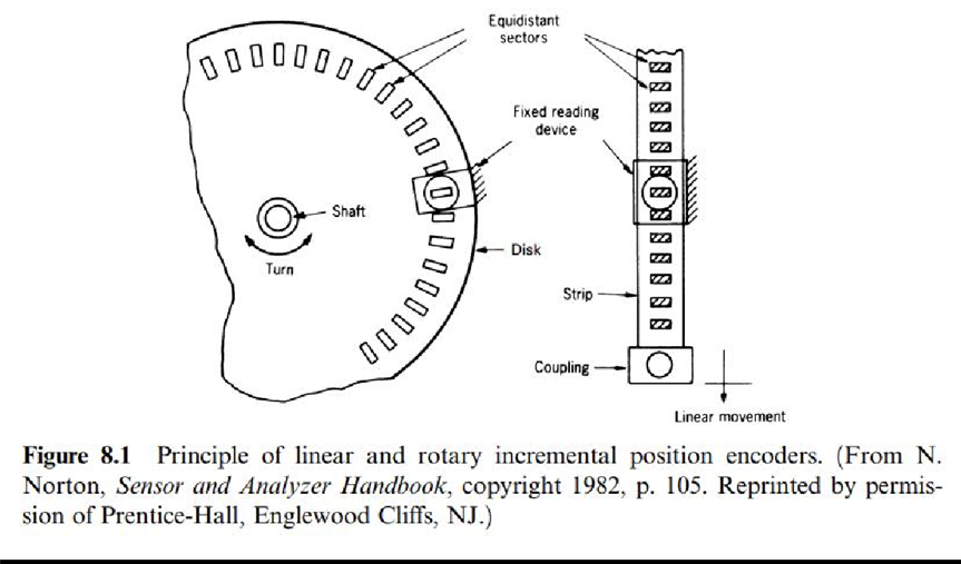
An incremental position encoder consists of a linear rule or a low-inertia disk driven by the part whose position is to be determined. That element includes two types of regions or sectors having a propertythat differentiates them, and these regions are arranged in a repetitive pattern (Figure 8.1).
Or
Incremental rotary encoder uses discs which contains transparent section that are equally spaced. A light-emitting diode serves a sender and it’s light is detected by a photo detector. Therefore, the encoder can generate a sequence of pulses. The output is measured in pulses per revolution which can be used to determine either the position or the rotational speed.
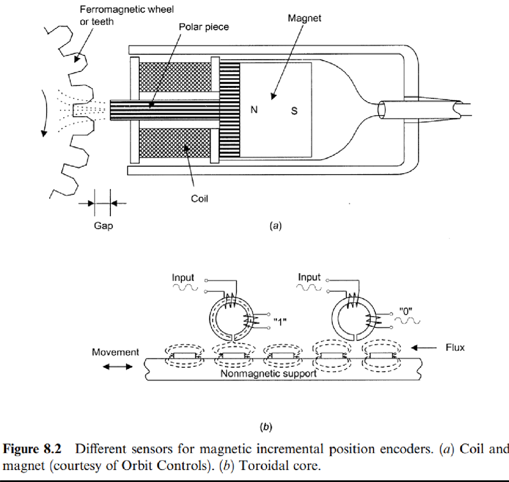
Figure 8.2b shows another inductive system but this time based on a toroid with two windings. One winding is used for exciting, using currents between 20 kHz and 200kHz, and the other is used for detection.
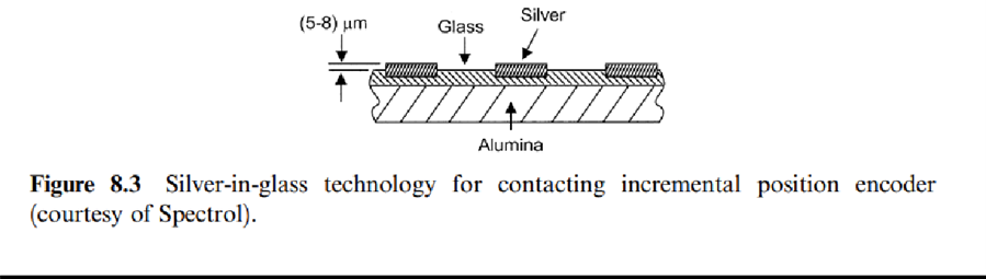
Silver-in-glass technology offers low cost, ruggedness, high-resistance to corrosion, and life expectancy of up to fifteen million cycles, far above the 100,000cycles of former PCB designs.
Optical encoders can be based on opaque and transparent regions, on reflective and non-reflective regions,and also on interference fringes.Whatever the case, the fixed reading head includes a light source (infrared LED), and a photodetector (phototransistor or photodiode).
Main problems (Disadvantages) result from dust-particle buildup, time and temperature drifts for electronic components, and vibrationeffects on focusing elements. High-performance sensors have either a lens or an aperture to provide collimated light output and minimal spurious reflections.
OPAQUE AND TRANSPARENT REGIONS
When opaque and transparent regions, chromium on glass, slotted metal, and so forth (Figure 8.4a) are used, the emitter and the receiver must be placed on each side of the moving element.
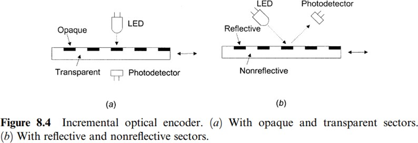
REFLECTIVE AND NON-REFLECTIVE REGIONS
In contrast, when relying on reflective and nonreflective zones, for example, polished steel with an engraved surface (Figure 8.4b) the emitter and the detector must be on the same side of the coding element. Glass disks are more stable, rigid, hard, and flat than metal disks, but are less resistant to vibrationand shock.
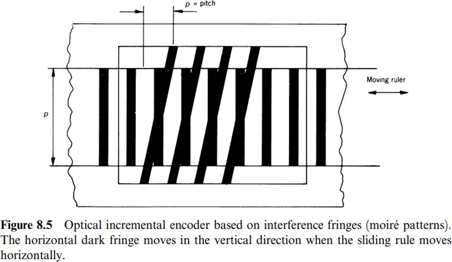
INTERFERENCE FRINGES
Interference fringe encoders are based on moire patterns. To create them from a linear movement, we can use a fixed and a movable rule having lines inclined with respect to each other (Figure 8.5).
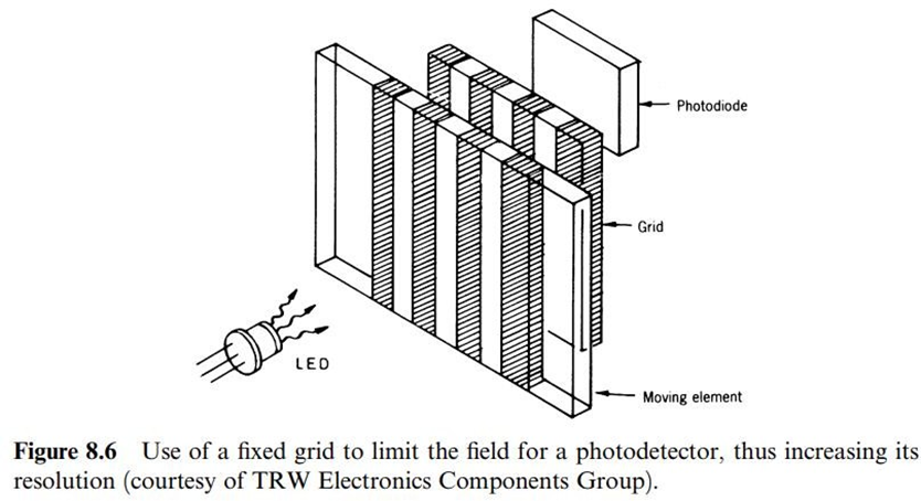
Optical encoders yield the highest resolution. The limiting factor is the photodetector size. Resolution increases by using one or several fixed grids or masks with opaque and transparent regions, placed between the movable elements and the detector, and having the same pitch as the encoded element(Figure 8.6 ).
4.1.2 ABSOLUTE POSITION ENCODERS
Absolute position encoders yield a unique digital output corresponding to each resolvable position of a movable element, rule, or disk, with respect to an internal reference. The movable element is formed by regions having a distinguishing property, and designated with the binary values 0 or 1. But unlike incremental encoders, their tracks are so arranged that the reading system directly yields the coded number corresponding to each position (Figure 8.11). Each track corresponds to an output bit, with the innermost track yielding the most significant bit. The most common sensors for these encodersare optical sensors.
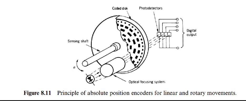
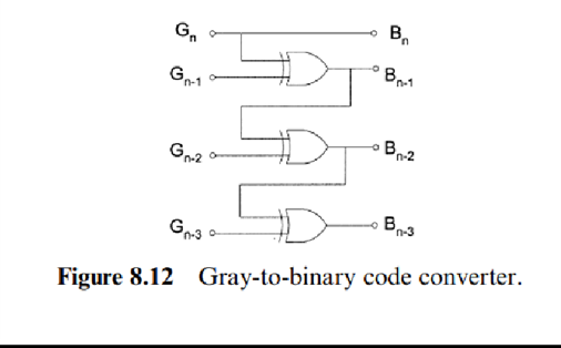
Figure 8.12 shows the corresponding circuit. The Gray code does not permit error correction for example, when transmitting signals in a noisy environment.
Common applications for absolute position encoders are high-resolution measurement and control of linear and angular positions.
They suit applications involving slow movements or where the movable element remains inactive for long time periods, such as parabolic antennas.
They are used, for example, in robotics, plotters, machine tools, read head positioning in magnetic storage disks, radiation source positioning in radiotherapy, radar, telescope orientation, overhead cranes, and valve control.
They can also sense any quantity that we convert to a displacement by means of an appropriate primary sensor for example, in liquid level measurements using a float.
4.2 RESONANT SENSORS
Sensors based on a resonantphysical phenomenon yield an output frequency that depends on a measurand (measured quantity) affecting the oscillation frequency. They require a frequency-counter in order to measure either the frequency or the oscillation period based on an accurate and stable clock. Resonant structures of single-crystal silicon are particularly suited to IC integration.
Sensors use eitherharmonic oscillators or relaxation oscillators.
Harmonic oscillators store energy that changes from one form of storage to another, for example from kinetic energy in a moving mass to potential energy in a stressed spring.
In relaxation oscillators there is a single energy storage form, and the stored energy is periodically dissipated through some reset mechanism.
Quartz clocks are accurate enough to derive a time base for most sensor applications, but they drift with time and temperature.
Time drifts arise from structural changes due to defects in crystal lattices, mechanical stress from supporting elements (that decrease as time passes and change after thermal cycling),and mass changesbecause of absorption and desorption of contaminant gases inside the crystal package.
4.3 SENSORS BASED ON QUARTZ RESONATORS
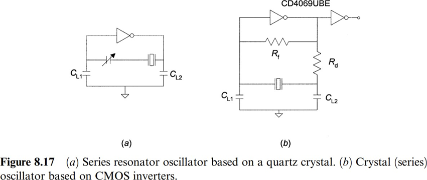
Quartz is piezoelectric and therefore an applied voltagestresses the crystal. If the voltage alternates at a proper rate, the crystal begins vibrating and yields a steady signal. C0 is the electrostatic capacitance of the crystal betweenthe electrodes plus the holder and the leads.
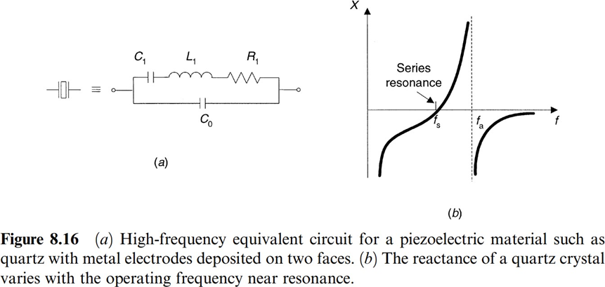
As the frequency increases, the crystal behaves as a positive reactance in series with a resistance. At the anti-resonant-frequency fa, the crystal's reactance is maximal. The range from fs to fa is referred to as the crystal's bandwidth. The series resonant circuit (Figure 8.17a) operates above fs, where the reactance is slightly inductive. Series capacitance is then added to tune the circuit. Figure 8.17b shows a basic oscillator based on CMOS inverters. Because quartz is inert, using a high-purity single crystal yields a mechanical resonance with large long-term stability.
DIGITAL QUARTZ THERMOMETER
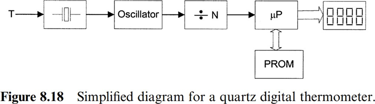
The values for the elements in the equivalent circuit for a quartz crystal depend on the temperature, and therefore the oscillation frequency displays a thermal drift. If precision-cut quartz crystals are used, the relationship betweentemperature and frequencyis very stable and repeatable.
QUARTZ MICROBALANCE
A quartz microbalance estimates a mass per unit area by measuring the change in resonance frequency. Open quartz microbalance can be used in liquid or air for biological or chemical sensing.
Quartz crystals oscillators are widely used as thin-film thickness monitors to control deposition rates and measurement of coating film thickness in the semiconductor and optical industries. They on a sensor functionthat considers the influence of the differentacoustic impedances of the deposition materials upon the resonant frequency.
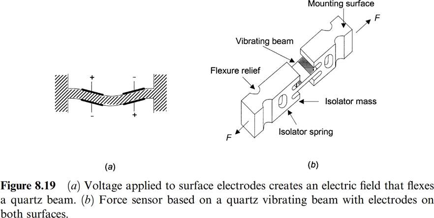
QUARTZ RESONATORS FOR FORCE AND PRESSURE SENSING
Quartz crystals, the same as other single-crystal materials, have highly stable elastic properties with very low creep and hysteresis. Hence, they suit mechanical resonators whose resonance frequency depends on the applied stress.
Quartz has the added advantage of being piezoelectric, so that the vibration can be excited by a driving alternating voltage.
Figure 8.19b shows a sensor for tensile and compressive force based on a single quartz beam.

QUARTZ ANGULAR RATE SENSORS
A vibrating quartz tuning fork can sense angular velocity because of the Coriolis effect.The sensor typicallyconsists of a double-ended quartztuning fork micromachined from a single quartz crystal(Figure 8.20) rotating at the angular velocity to measure, Ω. An oscillator at precise amplitude excites the drive tines so that they move toward and away from one another at a high frequency. Because of the Coriolis effect, there is a force acting on each tine,
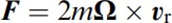
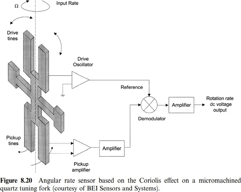
where m is the tine mass and vr is its instantaneous radial velocity.
Quartz angular rate sensors replacespinning-wheel gyroscopes becauseof their lower cost, increased reliability (there are no moving mechanical parts), and light weight.
It has been used to control angular velocity in aircraft, robots, and hydraulic equipment, to instrument automobile motions during crash tests, to evaluate rider quality in high-speed trains,to navigate autonomous underwater vehicles, to stabilize infrared cameras on helicopters, and in other applications.
4.4 SAW SENSORS
Just like an earthquake, Surfaceacoustic Wave or SAW is simply a mechanical wave confines to a solid interface. But these waves can exist at muchsmaller scales and can be used for a wide variety of applications.
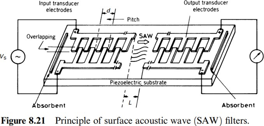
To generate SAW, we deposit metal onto a piezoelectric substrate and apply a voltage. This process can be reversed. An incoming wave will be picked up by the metal and create a measurable voltage.
The preferred piezoelectric materials for SAW sensors are quartz and LiNdO3.
Suppose a light bulb is connected to the output transducer. When SAW is picked up by the metal electrodes, it generates a measurable voltage and the bulb lights up. The glowing bulb shows output voltage at the transducer and only lights up when SAW ispresent.
The energy carried by the wave changes if it encounters a gas in it’s path. Different gasses will have different effect it shows in the light bulb. So, it’s possibleto know which gas has interacted with SAW by looking at the bulb.
SAW is used in smart phones, mobile communications, radio frequency filters and radar becauseof their simple design.
4.5 VIBRATING WIRE STRAIN GAGES
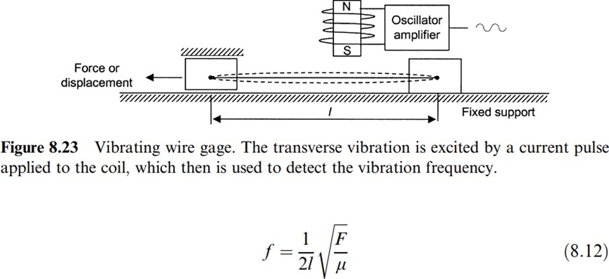
The lower transverse oscillation frequency for a vibrating taut (stretched, pulled or tight) string or wire of length l is where F is the mechanical force applied to it and µ is the longitudinal mass density (mass/length). If the position of one of the ends changes because it is mounted on a movable support, then the oscillation period is directly proportional to the displacement. If a force is applied, the resulting oscillation frequency is directly proportional. For strain measurement,
where E is Young's modulusand A is the wire'scross section.
This principle can sense any physical quantity resulting in a change in l, F, or m. A common application is strain or tension measurement [13]. In contrast with resistive strain gages, vibrating-wire strain gages can detect non-plane de-formation. In addition, they are insensitive to resistance changesin connecting wires for example,those due to temperature. Temperature interferes because it affects the sensing wire length l. In order to compensate for temperature, we can measure the change in resistance of the drivingcoil wire, as in RTDs.
Other reported applications are the measurement of mass, displacement, pressure (using a diaphragm with an attached magnet as primary sensor), force and weight (usinga cantilever as primary sensor).
Vibrating strips are used for dust deposition measurement of exhaustgases and also to measure viscosity.
4.6 VIBRATING CYLINDER SENSORS
If instead of a vibrating wire or strip we use a thin (75 mm)-walled cylinder with a closed end, the oscillation frequency depends on the dimensions and material for the cylinder and on any mass vibrating together with its walls.
By using an electromagnetic driver as in the previous case in order to keep the system oscillating, it is possible to measure the difference in pressure between both cylinder sides because it results in mechanical stresses in its walls.
We can also apply this system to gas density measurement because the gas near the walls vibrates when the walls do. For corrosive liquids it is better to use a glass or ceramic cylinder and a piezoelectric driver, thus avoiding corrosive-prone elements in electromagnetic drivers.
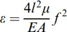
The most common application for this measurement principle is the measurement of the density of flowing liquids, using an arrangement like that in Figure 8.24. It consists of two parallel conduits through which the liquid flows; the two tubes are clamped at their ends and coupled to the main conduit by a flexible joint. Because the volume is known and the oscillation frequency for both conduits,which behave as a tuning fork.
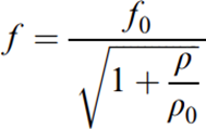
where f0 is the conduit oscillation frequency when there is no liquid, and ρ0is a constant that depends on system geometry.
4.7 DIGITAL FLOW METER
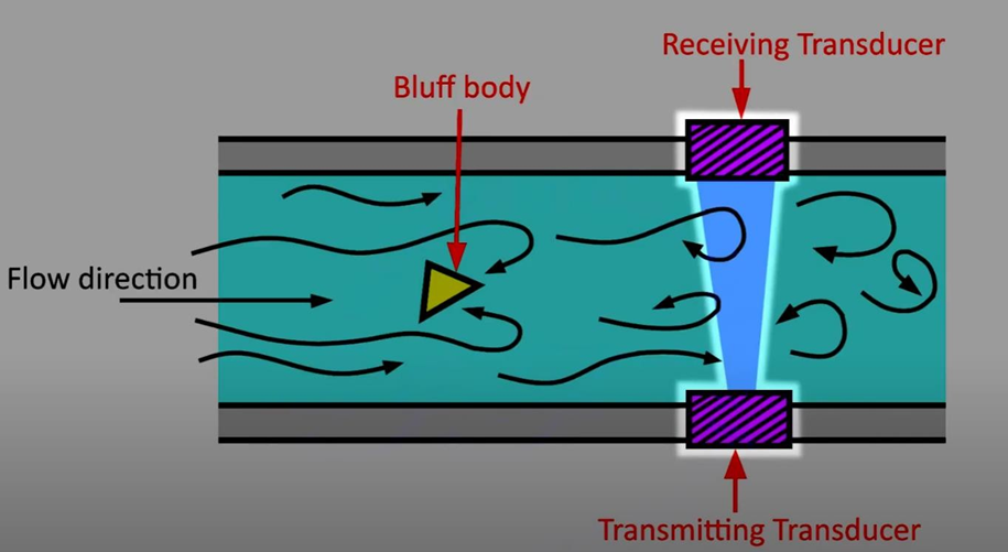
4.7.1 VORTEX SHEDDING FLOWMETERS
When a fluid stream enters a pipe with a conduit or bluffbody, the bluff body separates the obstruction and move around the obstructing body or bluff body in a vortex shedding flowmeter. Flow path is obstructed by bluff body that creates vortex swirls. The bluff body occupies less than 20% of inside diameter of the pipe.
Therate of vortex shedding is detected by an ultrasonic sensor that monitorschange in vortexpatterns by transmitting pulsating output signal.
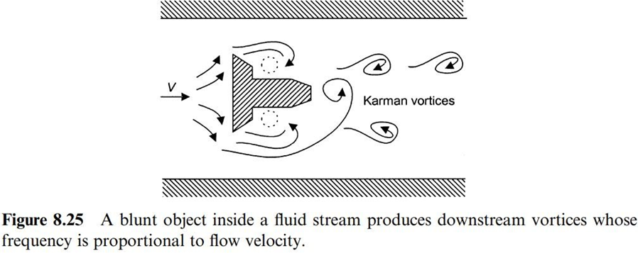
This method is fairly accurate(about 0.5 %) and independent of fluid viscosity, density, pressure, and temperature. It is particularly indicated forflow measurements at high temperature and high pressure.Its main shortcomings are that it introduces a large drop in pressure and that it is unsuitable for dirty, abrasive,or corroding fluids.
4.7.2 CORIOLIS EFFECT MASS FLOWMETERS
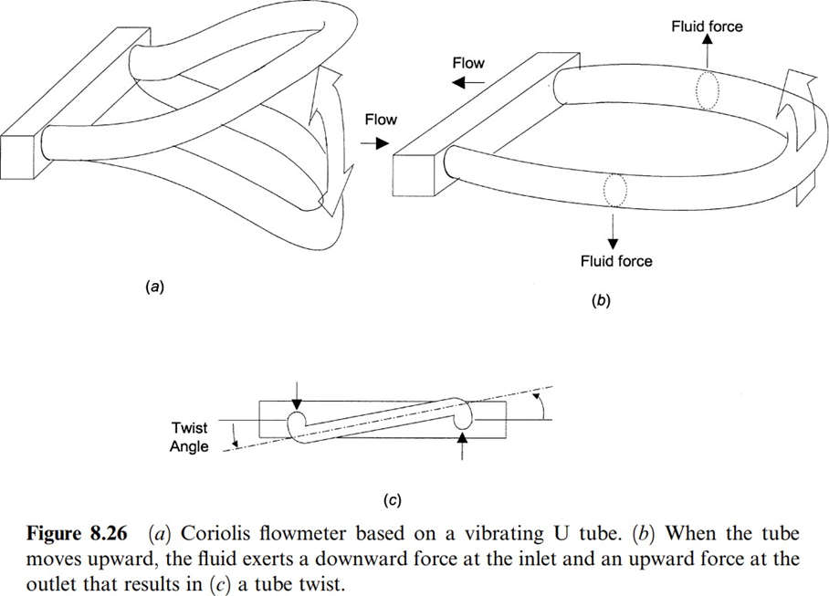
A common type of mass flowmeter relies on the Coriolis effect on a U- shaped flow tube (Figure 8.26 ) vibrated at its natural frequency (about 80 Hz) by an electromagnetic device located at the bend of the tube.
As the liquidflows into the tube, the Coriolis force it experiences because of the vertical movements of the tube has opposite sign to that experienced when it leaves the tube because opposite velocities yield opposite forces. That is, when the liquid enters the tube, it resists being moved upward (or downward) and reacts by pushing down (vise versa); when the fluid leaves the tube after having been forcedupward (or downward), it resists havingits vertical movement decreased and pushes up (respectively, down). The result is a tube twisting whose amplitude is proportional to the liquid mass flow rate.
Coriolis flowmeters measure mass directly, not through volume or velocity, and can measure corrosive fluids and difficult fluids such as slurries, mud, and mixtures.
They are not affected by changes in fluid pressure, density, temperature, or viscosity and can achieve an uncertainty of about 0.3 %. However, they are not useful for low-pressure gas because of the low forces they develop.
4.7.3 TURBINE FLOWMETERS
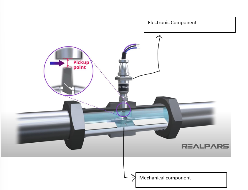
A turbine flowmeter consists of two components; mechanical component and an electronic component.
A turbine Flowmeter is inserted in a pipe directly in the flow path. The mechanical part of the Turbine flowmeter has a turbine rotor placed in the path of the flowing stream.The only moving part in the Turbine Flowmeter is the mechanical rotor.
The rotational speed of the rotor depends on the flow velocity. As the rotor spins, the passage of each rotor blade past a pickup point will generate an electrical pulse. The electrical pulses are createdin different ways depending upon the rotor blades themselves and the pickup unit characteristics.
In most turbine flowmeters, magnets are fitted to the rotor blades, and a magnetic pickup sensor is used to create the pulses. The higher the rate of flow the faster the rotor turns, and the greater the no. of pulses. The total number of pulses in a given time interval is proportional to the total volume displaced.
The shape and the voltage of the generated pulses depends on the type of pickup unit used.
Turbine flowmeters are used, for example, for fuel flow measurement in aircraft, in water service monitoring, and in monitoring spirometers.