Wireless Network and Communications 3rd Module
Characteristics of air interface
Radio Wave Propagation and Propagation Models
Before looking at any particular EM propagation models, a general overview of terrestrial EM propagation is warranted. EM waves below approximately 2 MHz tend to travel as ground waves. Launched by vertical antennas, these waves tend to follow the curvature of the earth and lose strength fairly rapidly as they travel away from the antenna. They do not penetrate the ionospicric layers that exist in the upper portions of the earth’s atmosphere. Frequencies between approximately 2 and 30 MHz propagate as sky waves. Bouncing off of ionospheric layers, these EM waves may propagate completely around the earth through multiple reflections or "hops" between the ground and the ionosphere. Frequencies above approximately 30 MHz tend to travel in straight lines or "Tays" and are therefore limited in their propagation by the curvature of the earth. These frequencies pass right through the earth's ionspheric layers. The daily and seasonal variations that occur in the characteristics of the ionospheric layers give rise to the repeated use of the word approximately in the previous explanations.
Other propagation considerations include antenna size and the penetration of structures by EM waves.
Antenna size is inversely proportional to frequency. The higher the frequency of operation the smaller the 1 antenna structure can be, which is an important consideration for a mobile device. Also, as frequency increases and wavelength decreass. EM waves have a mere difficult time penetrating the walls of physical structures in their path. At frequelicies above 20 GHz for example, signals generated within a room will usually be confined within the walls of a room. At even higher, frequencies, atmospherie water vapor or oxygen will attenuate the signal as it propagates through the atmosphere. These effects, although appearing detrimental at first, can be used to one's advantage for certain applications.
Wave Propagation Effects at UHF and Above
Since all of the world's mobile wireless systems use the UHF (300-3000 MHz) band, some additional details about propagation above 300 MHz will be given a: this time. Note also that the presently used ISM and U-NII bands are located in both the UHF and superhigh-frequency (SHF) bands (3-30 GHz). For sig-pal propagation both indoors and outdoors, three major effects tend to determine the final signal level that is received at the mobile station from the base station and the reverse case, the signal level received by the base station from the mobile. In theory, by what is known as the reciprocity theorem, the path loss for these two cases should be almost identical.
These three primary propagation effects are reflection, scattering, and diffraction. Reflection occurs for EM waves incident upon some type of large (compared tc a wavelength) surface. For a snooth surface the EM wave undergoes a specular reflection, which means that the angle of incidence equals the angle of flection.
Scattering occurs when the signal is incident upon a rough surface or obstacles smaller than a wavelength. This case produces what is known as a diff reflection (i.e., the signal is scattered in many different random directions simultaneously).
Finally, diffraction is a subtle effect that causes EM waves to appear to bend around corners. An EM wave incident upon sharp comer (e.g., the edge of a building rooftop) causes the generation of a weak point source that can illuminate a shadow or non-LOS (NLOS) area behind the object.
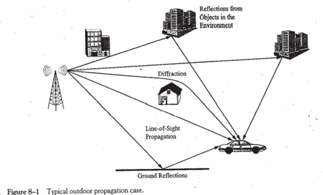
See Figure 8-1 for an example of an outdoor propagation case and Figure 8-2 for an example of a indoor propagation case. As shown by Figure 8-1 several signal paths may (and usually do) exist between the base station antenna and the mobile station. The primary signal tends to follow the line-of-sight (LOS path while several to many other secondary, tertiary, or higher-order reflections also arrive at the mobile. In addition, diffraction of the base station signal can occur from almost any type of object and therefore an number of diffracted signals might also arrive at the mobile.
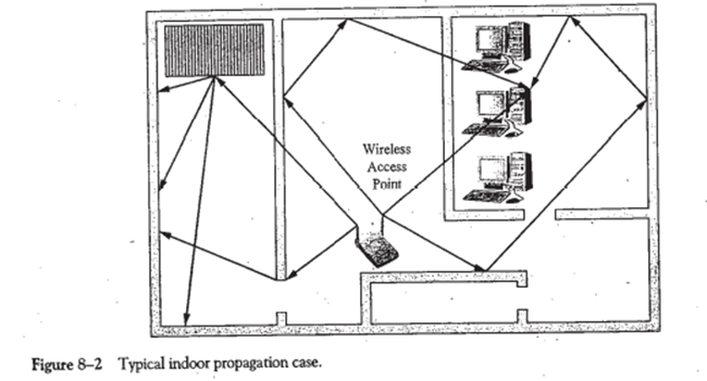
Figure 8-2 shows an example of an indoor propagation situation similar to what might be encountered with a wireless LAN access point and a wirelessly enabled laptop. In this case, the signal from the transmit-propagates through the walls between the rooms, experiences numerous reflections off of wails in a corridor and other interior walls, and undergoes diffraction and scattering due to various other obstacles lid sharp corners. Again, all the signals arriving at the receiver will add together vectorially to create the composite received signal. For this case, due to the short propagation distances involved, there will be only small spread of delays between the arriving signals. This important point will be expanded upon shortly.
Path Loss Models
The first path loss model to consider is that for free space propagation. It may be shown fairly easily that without any outside influences the propagating signal power of an EM wave decreases by the square of the distravelledaveled as it spreads out. Therefore, the EM wave undergoes an attenuation of -5 dB every time the distance it travels doubles. The power received from an antenna radiating Pr watts in free space is given b the following equation (known as the Friis equation)

where G7 and GR are the transmitting and receiving antenna link gains, respectively, A is the signal wave-length, and d is the distance from the transmitting antenna. A typical technique to simplify the usage of this equation is to rewrite it as:

where Po is the received signal strength at a distance of one meter. Once Po has been calculated, it is a simple task to determine the received signal strength at other distances. Also important to note here is that in the free space environment the velocity of propagation for an EM wave translates into an approximately 33-ns-per-meter time delay. This means that it takes 3300 ns for a signal to travel a distance of 1000 meters in free space. This fact will be called upon later in our further discussions about multipath propagation. At this point, a free space path loss example is appropriate.
Then from Equation 8-2,

The path loss in dB is the difference between the transmitted power, Pr, and the received power, Pr. Or, in equation form:

For this particular example, the path loss is equal to +30 dBm (-63.934 dBm) or 93.934 dB. Note, IW = +30 dBm.
Explain the following
Explain wireless telecommunication coding technique
(i) Error Detection and Correction Coding
Sa Error detection and correction codes designed for wire-line systems and wireless systems tend to differ in their basic implementation. Error control coding is the term used to denote a technique that codes the transmitted bits in a way that attempts to control the overall bit error rate.
The type of coding used is also somewhat dependent upon the maximum bit error rate that can be tolerated. For the latter case, if low enough bit error rates cannot be achieved, a means by which the system can ask for a retransmission of a data packet when necessary must be designed into the system schemes.
Block codes may be used to determine whether an error has occurred during data transmission. Today block convolutional and turbo codes are used to enhance the transmission of packet data over wireless systems
(ii) Speech Coding
Speech Coding is used for both GSM and CDMA wireless systems take 20-msec segments of either previously encoded speech or raw speech and process it into lower bit rate digitally encoded speech in preparation for its transmission over the air interface. There are many different types of speech encodes available today.
In general there are two broad classification of speech codes: waveform coder and vocoders. Pulse code modulation is an example of a waveform coder whereas the QCELP encoder used in IS-95 CDMA or the RPE-LTP encoder used in GSM are examples of vocoders.
(iii) Block interleaving
Block interleaving is a technique used by mobile wireless systems to combat the effects of bit errors introduced during transmission of a frame. The basic idea here is that error control code used by the system may be able to correct one bit error out of 8 bits.
However, it is not able to correct a burst of say six errors within the 8-bit block.
If the bit of the block can be interleaved with the bits from other blocks, then in theory the burst of six errors can be spread out over six other blocks and the ECC can correct each of the single bit errors in each of the six blocks
Explain Error detection and correction coding techniques in wireless technologies
Block Codes
A simple view of block coding is that the system takes a block of data bits and encodes then into another block of bits with some additional bits that are used to detect or combat errors.
The simplest form of this technique is through the use of a single parity bit.Using even or odd parity, a single error can be detected.However it easy to see that multiple errors may not be detected.
Using more sophisticated techniques, additional bits may be generated through a matrix or polynomial generator and added to the original block of bits to form a code word that will be eventually transmitted by the system.
A code word generated by a polynomial is a form of cyclic code and codes of this type are known as cyclic redundancy check (CRC) codes. Depending upon the type of coding level employed these schemes can bot detect and correct limited numbers of errors
Convolutional Encoders
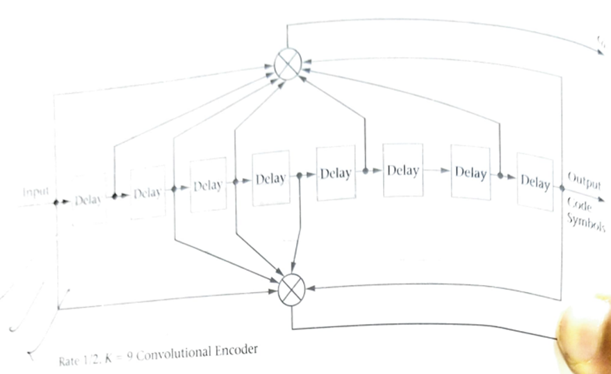
A convolutional encoder does not map blocks of bits into code words. Instead, a continuous stream of bits is mapped into an output stream that now possesses redundancy. The redundancy introduced to the bit stream is dependent upon the incoming bits and several of the preceding bits
The number of preceding bits used in the encoding process is known as the constraint length K, and the radio of input bits to output from the encoder is known as the code rate R of the encoder.
Some systems use both block coding techniques and convolutional encoders to generate the final transmitted data packet. Fig 8.5 shows in block diagram from an implementation of a convolutional encoder
Turbo Encoders
Turbo encoders are a modified form of combined convolutional encoders that can be used to create a new class of enhanced error correction codes.
A typical turbo encoder is constructed from two systematic, recursive, convolutional encoders connected in parallel with an interleaver receding the input to the second convolutional encoder. The output bit streams of the two convolutional encoders are multiplexed together and repeated to form the final code symbols
Explain OFDM digital modulation techniques
Orthogonal frequenct division multiplexing is really a form of multicarrier, multisymbol,multirate EDM in which the user gets to use all the EDM channels together. The term OFDM comes from the fact that the carriers of the EDM channel possess the property of orthogonality.
Orthogonality implies that orthogonal signals will not interfere with each other at a receiver. This simple but extremely important concept can be used to enhance packet data transfer rates over fixed EDM transmission systems.
The implementation of an OFDM system is fairly straightforward. Instead of attempting to transmit N symbols per second over a single forward carrier link. M carriers are used to transmit N/M symbols per second, which ends up yielding the same data transfer rate, N.
Additionally, the frequent spacing between each carrier is chosen to satisfy the orthogonality criteria. For each carrier, a multisymbol digital modulation scheme is used to transmit more than 1 bit per symbol time.
Another feature of an OFDM system would be the ability for the system to sense the radio channel quality and be able to fall back to lower data rates as needed. This can be done with multirate modems that only transmit as many bits per symbol as the C/I rate allows.
As the user moves away from an access point, the C/I ratio usually decreases and the multisymbol, multirate modem used by the system changes to a lower but useable data rate.
Explain Spread Spectrum Modulation Techniques
There are two basic ways of implementing spread spectrum transmission:
(I) Frequency Hopping spread spectrum
Frequency Hopping spread spectrum consists of a system that changes the centre frequency of transmission on a periodic basis in a pseudorandom sequence.
There are usually a limited number of different carrier frequencies to hop to and the hopping sequence is designed in such a fashion as to keep the occurrence of the various hopping frequencies statistically independent from one another.
For the system to work both the transmitter and receiver must have prior knowledge of the hopping sequence. Fig 8.15 shows an example of FHSS system
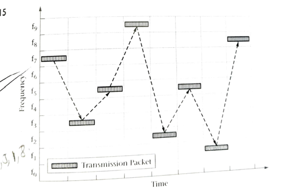
As the transmitter implements the hopping sequence the effective signal bandwidth increases to include all of the utilized carrier frequencies. However, the instantaneous bandwidth is just that of a single modulated carrier.
The use of FHSS does not provide any improvement in a noise free environment. However for the situation where narrowband noise exists or deep frequency selective fading is prevalent, the FHSS scheme will allow only a small fraction of the transmitted data to be corrupted while the rest of the transmitted information remains free.
(II) Direct Sequence Spread Spectrum
The second form of spread spectrum is direct sequence spread spectrum. In this case a spreading code is applied to the baseband DataStream at the transmitter and the same spreading code is applied to the received signal to perform demodulation.
As with FHSS both the transmitter and reliever must have knowledge of the “key” spreading code in use for the DSSS system to work properly.
Since the spreading chips are many times shorter in duration than the baseband bits that they are encoding and spreading, the final transmitted signal now consists of many more bits or symbols per second than the original data stream.
The number of chips per second now determines the basic bandwidth of the transmitted signal.
To improve the noise immunity characteristics of wireless mobile DSSS systems and to allow more than one signal to be transmitted on the same carrier frequency simultaneously, special orthogonal Walsh codes are used as part of the spreading process
Explain QPSK modulation technique
Quadrature phase shift keying (QPSK) is another modulation technique, and it’s a particularly interesting one because it actually transmits two bits per symbol. In other words, a QPSK symbol doesn’t represent 0 or 1—it represents 00, 01, 10, or 11.
This two-bits-per-symbol performance is possible because the carrier variations are not limited to two states. In ASK, for example, the carrier amplitude is either amplitude option A (representing a 1) or amplitude option B (representing a 0). In QPSK, the carrier varies in terms of phase, not frequency, and there are four possible phase shifts.
We can intuitively determine what these four possible phase shifts should be: First we recall that modulation is only the beginning of the communication process; the receiver needs to be able to extract the original information from the modulated signal. Next, it makes sense to seek maximum separation between the four phase options, so that the receiver has less difficulty distinguishing one state from another. We have 360° of phase to work with and four phase states, and thus the separation should be 360°/4 = 90°. So our four QPSK phase shifts are 45°, 135°, 225°, and 315°.
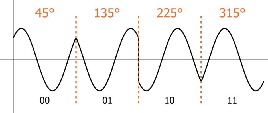
Compared to modulation schemes that transmit one bit per symbol, QPSK is advantageous in terms of bandwidth efficiency. For example, imagine an analog baseband signal in a BPSK (binary phase shift keying) system. BPSK uses two possible phase shifts instead of four, and thus it can transmit only one bit per symbol. The baseband signal has a certain frequency, and during each symbol period, one bit can be transmitted. A QPSK system can use a baseband signal of the same frequency, yet it transmits two bits during each symbol period. Thus, its bandwidth efficiency is (ideally) higher by a factor of two.
Explain different diversity techniques (Any two)
Specialized Receiver Technology (Rake Reciever)
A Rake Receiver is a radio receiver which is designed for the purpose to counter the effects of multipath fading. Due to reflections from multiple obstacles in the environment, the radio channel can consist of multiple copies of the transmitted signal having different amplitude, phases or delays.
A rake receiver can resolve this issue and combine them. For this purpose, several sub-receivers are used which are known as “fingers”.
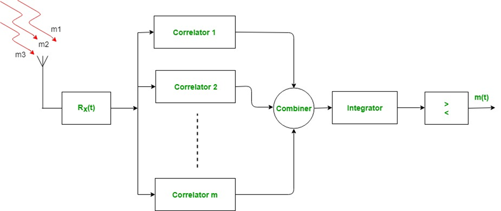
When the transmitter transmits the signal then it travels through the environment which consists of various obstacles and the transmitted signal is reflected by them and is received by the rake receiver from multiple paths. Rake receiver then feeds them to different fingers (correlators). The delays in each received signal are compensated and are feeded to the Combiner, Integrator and Comparator which combines them suitably with different appropriate time delays.
Modern Digitally implemented RAKE receivers used in today’s CDMA wireless mobile systems may only have a few RAKE taps but possess the ability to dynamically adjust the taps in response to a search algorithm used to locate multipath components.
These smart receivers can generate several signals that can be further combined by several standard diversity combining techniques to provide a more reliable receiver output and therefore improve system performance.
Space Diversity
A typical technique used to improve mobile wireless system performance is to employ space diversity in the form of addition receiving antennas located at the base station.There are many ways to achieve the needed space diversity at the base station site. Fig shows several practical implementations
As can be seen in the figures,both space and polarization diversity can be used by the appropriate positioning of the antenna units. The antennas feed multiple receivers, with the strongest recived signal being used by the system
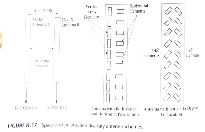
This technique is universally implemented by wireless mobile service providers in the design of their systems. Polarization diversity is used to counter the change in EM signal polarization that can be induced by the environment during reflection, scattering and so on.
Smart Antennas
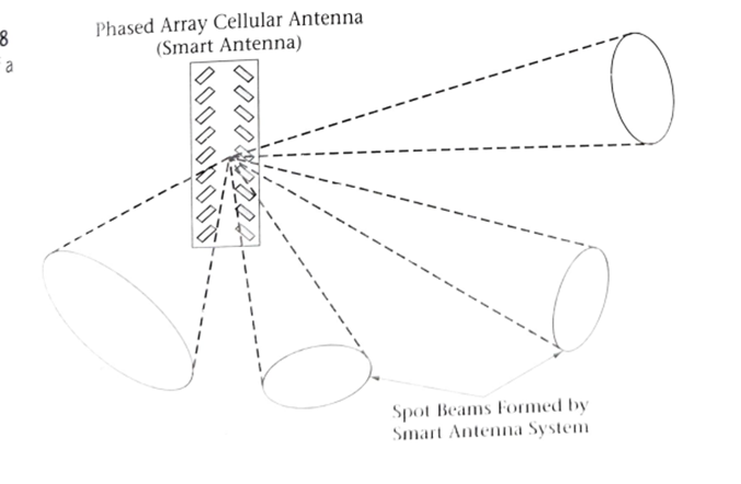
In the 3G specifications, the support of smart antenna technology is included. This technique to improve system performance makes use of phased array or “beam steering” antenna systems.
These types of antennas can use narrow pencil-beam patterns to communicate with a subset of the active users within a cell. Once a mobile subscriber has been located by the system, a narrow radio beam may be pointed in the user’s direction through the use of sophisticated antenna technology.
The use of a radio link that approaches point to point type link characteristics is extremely useful in a mobile environment. Besides the elimination of most multipath signals, a fact that will certainly improve system performance, the amount of interference received will be reduced and system capacity can be increased.
Single antenna Interference Cancellation
Single Antenna interference cancellation (SAIC) is a newly developed technique that can be used to improve the downlink performance of a GSM system. To fully benefit from this technology the GSM system should be synchronous.
SAIC use either of two sophisticated algorithms to cancel interference for the dominate interferer. The two types of techniques that can be used are known as joint detection and blind interference cancellation (BIC).
In both cases, the systems tend to suppress interference that would normally cause bit error rate of the system. Hence the overall system BER characteristics improved
Write a note on GSM Hardware
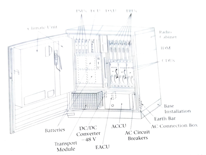
Housed in standard radio relay rack frame configurations, the typical BSC/TRC or RNC can manage a number of radio base stations in a serving area of a GSM or 3g UMTS network.
The typical RBS is located at the cell site and consist of either a self contained, environmentally conditioned, stand-alone unit that can be located outdoors on a concreted pad or a unit housed in standard radio relay rack for placement in a controlled environement structure with other equipment
Explain Ultra wideband radio technology
Using ultra wideband technology allows for the overlay of novel radio services into pre-existing frequency bands. This technology is extremely well suited for the short range application space. Its use is predicated on the innovative approach of effective sharing radio frequency spectrum instead of looking for new frequency bands for new services.
At this time, a number of potential uses of UWB technology have been identified. A brief list includes imaging systems, vehicular radar, measurement and positioning systems and data communications
Using extremely narrow pulses UWB radio systems are able to provide high data rate (100-500mbps) transfers over short distances (1-10 meters). At the same time, the bandwidth of such a high-data-rate UWB system may extend over several to many GHz within the FCC allocated 3.1 to 10.6 GHz range


