
Wireless Network and Communications 4th Module
WLAN (Wireless local area network)
Wireless local area network (WLANs) are flexible data communication systems implemented as extensions to or as alternatives for wired local area networks (LAN).
The networks that cover a distance of 10-500m are called WLANS
Network Architecture
There are two modes of WLANs:
Infrastructure based WLAN
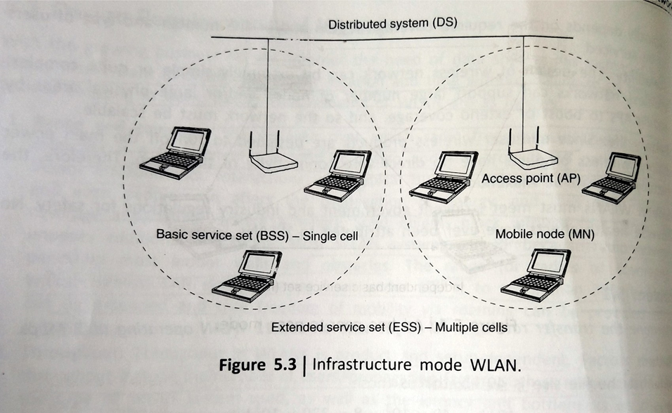
A typical infrastructure based WLAN defines two pieces of equipment: a wireless station (WSTA) which is usually a PC equipped with a wireless network interface card (NIC) and an AP, which acts as a bridge between the wireless and wired networks.
An AP usually consists of a radio, a wired network interface(e.g. 802.3) and a bridging software conforming to the 802.1d bridging standard. The AP acts as the base station for wireless network aggregating access for multiple WSTAs onto the wired network.
In infrastructure mode (fig 5.3), the wireless network consists of at least one AP connected to the wired network infrastructure and a set of wireless-end stations. This configuration is called basic service set
The infrastructure network provides an architecture for providing communication between wireless clients and wired network resources. Infrastructure- based wireless networks use fixed network Aps with which mobile clients can communicate
Infrastructure less WLAN
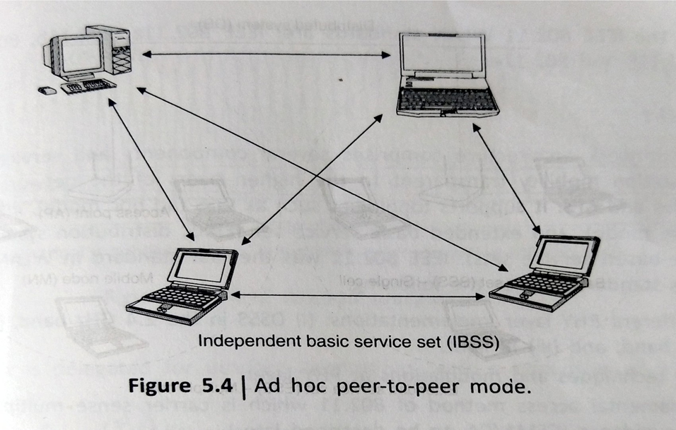
These are sometimes reffered to as ad hoc networks, as they are temporary networks established as and when required. There are two kinds of ad hoc networks: peer-to-peer and multihop. The components are similar to those used in infrastructure based LANs with the exemption of Aps
Ad hoc mode also called as peer to peer or independent basic service set is simply a set of WSTA that communicate directly with one another without the use of Aps or any connection to a wired network as shown in fig.
This mode is useful for quickly and easily setting up a wireless network where a wireless infrastructure does not exist or is not required for services such as a hotel room, a convention center or an airport.
Network Components
The Main component of WLAN are
WLAN Adapter
Wireless adapters are made in the same basic form factors as their wired counterparts. They usually contain the functionallities of physical (PHY) and data link layers. They enable end to end users to access the network. In a WLAN, adapters create a transperant connection to the network.
Access Points
Essentially, the access point (AP) is the wireless equivalent of a wired local area network(LAN) hub. It reveives, buffers and transmits data between the WLAN and the wired network supporting a group of wireless user devices. An AP is typically connected with wired backbone through a standard Etharnet cable and communicates with wireless devices by means of an antena.
AP covers a range of 20-500 meters and a single AP can support between 15 and 20 users depending upon the technology,configuration and use.
Outdoor WLAN Bridges
These are used to connect wired LANs in different buildings. The cost of deploying a fiber optic cable between buildings is high in situations where barriers exist between the buildings such as highways,bodies of water,valley etc.
In such situations, a WLAN bridge can be an economical alternative. A bridge can also provide a less expensive alternative to recurring leased line charges. WLAN bridge supports fairly high data rates and covers ranges of several miles with the use of line of sight directional antennas.
WLAN routers
The basic function of the router is to transfer the packets between the networks. The roter chooses the next best link to send packets in order to reach closer to the final destination.
Routers use Internet protocols (IP) packet headers and routing tables as well as IPs to determine the best path for each packet. A WLAN router adds a built in AP function to a multiport Ethernet router. This combines multiple Etharnet networks with wireless connectons as well.
Design Requirements of WLAN
Design requirements of WLAN are
- Range and coverage: The design over which radio frequency (RF) waves can communicate is a function of the product design and the propagation path, especially indoor environments. Most WLAN systems use RF because radio waves can penetrate most indoor walls and obstacles.
The range of typical wireless LAN varies from under 100 ft to more than 300 ft. Coverage can be extended and true freedom of mobility via roaming can be provided through microcells
- Compatibility: WLANs should provide industry-standard interconnection with wired networks such as Ethernet or token ring. WLAN nodes should be supported by network operating systems in the same fashion as any other LAN node through the use of appropriate drivers.
- Licensing issues: For WLANs to be sold in a particular country, the manufacturer the WLAN must ensure its certification by the agency in that country.
- Security: Security has long been a design criterion for wireless devices. Security provisions are typically built into WLANs, making them more secure than most wired LANs. It is extremely difficult for unintended receivers to listen WLAN traffic.
- Cost: A WLAN implementation should look at the cost which includes both infrastructure, for the wireless access points, and user costs, for the WLAN adapters. Infrastructure cost depends upon number of AP deployed
- Scalability: The design of wireless network can be extremely simple or quite complex. Wireless networks can support large number of nodes and/or large physical areas by adding Aps to boost or extend coverage, and so on the network must be scalable
- Battery life: Since end-user wireless products are designed to run off the main power supply, wireless products have no direct wire connectivity of their own. Therefore, the battery life must be maximum
- Safety: WLANs must meet stringent government and industry regulations for safety. No adverse health effects have ever been attributed to WLANs
WLAN Protocols
IEE 802.11
Layer Description of IEE 802.11
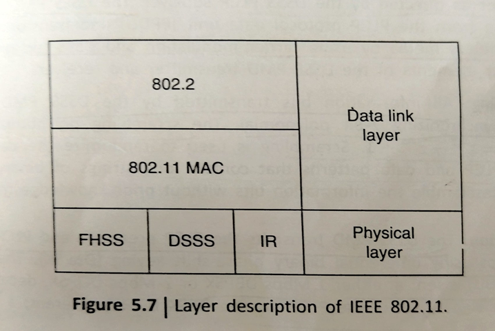
The IEEE 802.11 standard places specifications on the parameters of both the PHY and MAC layers of the WLANs.A layer description of IEEE 802.11 is given in fig. The PHY layer of IEEE 802.11 standard actually handles the transmission of data between nodes; it can use either of the following encoding schemes: DLSS, 1-2 Mbps; FHSS, 1-2 Mbps; IR pulse position modulation, 1-2 Mbps; OFDM at 54Mbps and DSSS at 2.4 GHz with 11 Mbps.
Description of PHY layer of 802.11
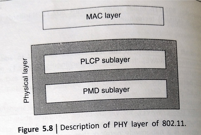
The PHY layer is the interface between the MAC and wireless media ,which transmits and receives data frame over a shared wireless media .As shown in fig the phy layer IEEE 802.11 consists of two sublayers: the physical medium-dependent (PMD) sublayer and the PHY layer convergence (PLCP) sublayer on top.
The PMD specifies how to send and receive data over the wireless medium and the PLCP layer maps the MAC frames to the PMD functions. The PHY layer provides three layer of functionality; First, it provides a frame exchange between the MAC and the PHY under the control of the PLCP sublayer. Second it uses signal career and spread spectrum modulation to transmit data frames over the media under the control of PMD sublayer. Third, it provides a carrier sense indication back to the mac to verify the activity on the media.
Frequency hopping spread spectrum (FHSS) PHY: The FHSS uses 2.4 ghz frequency band as the RF transmission data media. Data transmission over the media is controlled by the FHSS PMD sublayer as directed by the FHSS PLCP sublayer. The FHSS PMD takes the binary hits of information from the whitened protocol service data unit (PSDU) and transforms them into RF signals for the wireless media by using carrier modulation and FHSS techniques.
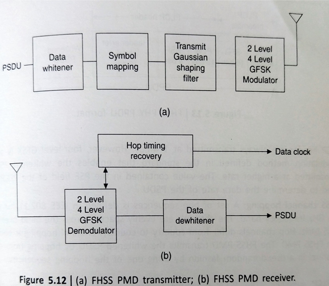
Fig illustrates the following basic elements of the FHSS PMD transmitter and reciever:
- PSDU data whitening: Data whitening is applied to the PSDU before transmission to minimize DC bias on the data if long strings of 1s or 0s are contained in the PSDU
- FHSS modulation: 802.11 uses two level Gaussian frequency-shift key (GFSK) in the FHSS PMD to transmit the PSDU at the basic rate of 1 Mbps
- FHSS channel hopping: A set of hop sequences is defined in IEEE 802.11 for use in the 2. Ghz frequency band. Channel hopping is controlled by the FHSS PMD
FHSS PLCP sublayer: The PLCP preamble is used to acquire the incoming signal synchronise the reciever’s demodulator.Fig illustrates the format of an FHSS PHY PPDU.
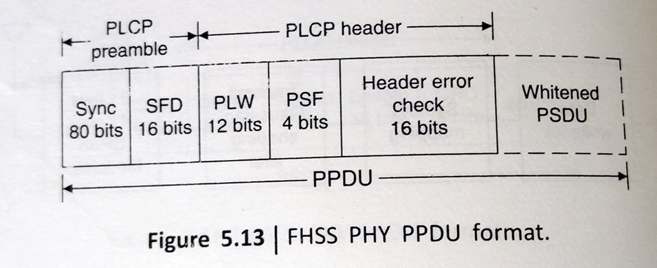
The data items in FHSS PPDU are as follows:
- SYNC: This field contains a string of alternating 0 and 1 patterns and is used by the reciever to synchronise the reciever’s packet timing and correct for frequency offsets
- SFD: This field contains information marking the start of a PSDU. A common SFD is specified for all IEEE 802.11
- PSDU length word (PLW): This field specifies the length word of the PSDY in octets and is used by the MAC to detect the end of a PPDU frame
- PLCP signaling field (PSF): The PSF identifies the data rate of the whitened PSDU ranging from 1 to 4.5 Mbps in increments of 0.5 Mbps.The PLCP preamble and header are transmitted at the basic rate of 1 Mbps
- Header check error: This field contains the results of a calculated frame check sequence from the sending station.The calculation is performed prior to data whitening
WLAN Applcaitions
-Office/ campus environment
-Factory Shop Floor
-Homes
- Workgroup Environment
-Heritage Buildings
-Public Places
-War/Defense Sites
Wireless MAN
Wireless MAN is a promising broadband wireless access (BWA) technologt that provides high-speed,high bandwidth efficiency and high-capacity multimedia services for both residential and enterprise applications
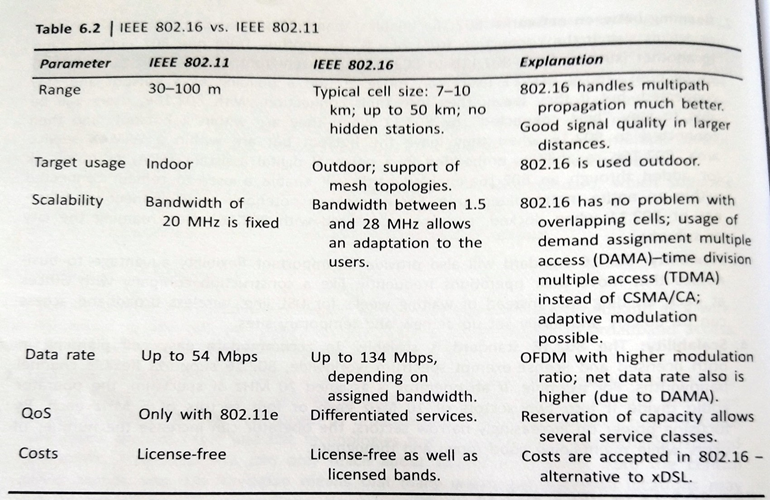
IEEE 802.16 vs IEEE 802.11
WMAN Network Architecture
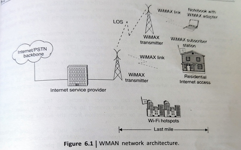
WiMAX is a separate radio system that is designed to either supplement or replace the existing broadband Internet distribution systems. Fig shows a typical WiMAX system network architecture. With a distributed WiMAX network architecture, the WiMAX system simply becomes an extension of the Internet or public switched telephone network to the mobile user.
Leveraging simple IP based backhaul connections, ISP can very readily service a WiMAX base sit via WMAX transmitters for varying coverage and capacity profiles addressing outside environments, inside buildings and fixed and fully mobile connections.
The cell equipment in the WiMAX BS compromises the basic BS equipment, radio equipment and a BS Link to the backbone network. The BS is what actually provides the interface between the mobile users (WI-FI hotspots or notebook with WiMAX adapter) and the WiMAX network.
The coverage radius of a typical BS in urban areas is around 500-900m. Network service providers will simply expand their networks based on system usage leveraging standard IP components
Network Components
- WiMAX base station: A WiMAX BS consists of indoor electronics and a WiMAX tower. A WiMAX BS can provide coverage to a very large area up to a radius of 6 miles. Any wireless device within the coverage area would be able to access the internet
The WiMAX Base stations would use the MAC layer defined in the standard. A common interface makes the networks interpolate and would allocate uplink (UL) and downlink (DL) bandwidth to subscribers according to their needs or an essentially real time basis. Each BS provides wireless coverage over an area called a cell. Theoretically, the maximum radius of a cell is 50km or 30 miles; however practical considerations limit it to about 10km or 6 miles.
- WiMAX receiver: A WiMAX receiver may have a separate antenna or could be a standalone box or an interface card sitting on the laptop or computer or any other device. This is also referred to as customer premise equipment
An 802.16 based system often uses fixed antenna at the SS site. The antenna is mounted on the roof. A Base station typically uses either sectored/directional antenna whereas a mobile or portable SS usually uses an omnidirectional antenna.
- Backhaul: A WiMAX tower station can connect directly to the internet using a high bandwidth wired connection. It can also connect to another WiMAX tower using a LOS, microwave link. Backhaul refers to the connection from the access point to the BS and from the BS to the core network.
It is possible to connect several Base stations to one another using high speed backhaul microwave links. This would also allow for roaming by a WiMAX subscriber from one base station coverage to area to another, similarly to the roaming enabled by cell phones.
Features of WiMAX (Requirements)
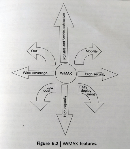
1. Flexible architecture: WiMAX supports several system architectures, including p2p,p2mp and ubiquitous coverage. The WiMAX MAC supports P2MP and ubiquitous service. IF there is only one SS in the network, the WiMAX BS will communicate with the SS on a P2P basis
2. High security: WiMAX supports advanced Encryption standard and Triple encryption standard. By encrypting the links between the BS and the SS, WiMAX provides subscribers with privacy (against eavesdropping) and security across the broadband wireless interface.
3. WiMAX Qos: WiMAX can be dynamically optimized for the mix of traffic that is being carried. Five types of services are supported:
unsolicited grant service,
polling service,
extended real time polling service,
non real time polling service,
best effort service
4. Quick Deployment: WiMAX requires little or no external plant construction. Deployment of WiMAX can be completed in a matter of hours compared with months for other solutions
5. Multilevel service: The manner in which QoS is delivered is generally based on service level agreement between the service provider and end user
6. Portability: Once the WiMAX SS is powered up, it identifies itself, determines the characteristics of the link with the BS as long as the SS is registered in the system database and then negotiates its transmission characteristics accordingly
7. Cost-effective: WiMAX is based on an open international standard. Mass adoption of the standard and the use of low cost mass produced chipsets, will bring costs down dramatically
8. High capacity: Using higher modulation and channel bandwidth, WiMAX systems can provide significant bandwidth to end users
Network Protocols
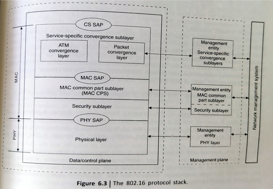
The 802.16 protocol stack is shown in fig 6.3. The IEEE 802.16 standard is structured in the form of a protocol stack with well-defined interfaces. The MAC layer is formed with three sublayers:
- Service specific convergence sublayer
- MAC common part sublayer
- Privacy sublayer
The MAC CS receives higher level data through CS service access point and provides transformation and mapping into MAC service data unit.MAC SDUs are then received by MAC CPS through MAC SAP.
The MAC CPS is the core part of the MAC layer, defining medium access method. The CPS provides functions related to duplexing and channelization, channel access, packet data unit (PDU) framing, network entry and initialization.
The privacy layer lies between the MAC CPS and the PHY layer. Security is a major issue for public networks. The sublayer provides the mechanism for encryption and decryption of data transferring to and from PHY later and is also used for authentication and secure key exchange. Data, PHY control and statistics are transferred between the MAC CPS and the PHY layer through the PHY SAP
WMAN Applications
Banking Networks
Educational institutions
Wireless Service Provider backhaul (city wide internet)

